D
dpierceJul 31, 2025
What to do if the torch body is cracked on my Miller XMT 450 CC/CV Welding System?
- XxaviervaughnJul 31, 2025
If the torch body of your Miller Welding System is cracked, the suggested solution is to replace it.
What to do if the torch body is cracked on my Miller XMT 450 CC/CV Welding System?
If the torch body of your Miller Welding System is cracked, the suggested solution is to replace it.
Explains hazard symbols and covers electrical shock and grounding safety.
Addresses fumes, gases, arc rays, fire, explosion, and flying debris risks.
Covers hazards from cylinders, moving parts, batteries, and installation/operation.
Discusses RF/arc interference, EMF, Proposition 65, and safety standards.
Explains additional safety symbols and warnings.
Defines various welding symbols, abbreviations, and terms.
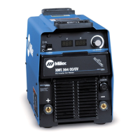
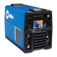
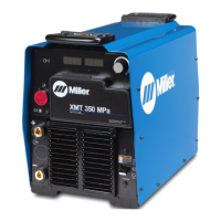
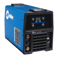
Describes unit features, arc controls, and label locations.
Lists unit specs, dimensions, weight, and environmental ratings.
Explains duty cycle limits and overheating procedures.
Displays voltage and amperage output capabilities for different modes.
Guidance on choosing a suitable installation site and airflow.
Instructions for setting the input voltage for 230/460V models.
Guidelines for cable sizing and connecting output terminals.
Step-by-step guide for connecting input power.
Describes the controls and displays on the front panel.
Explains the different welding modes and their settings.
Illustrates the standard setup for GTAW welding.
Details the setup and operation of Scratch Start TIG.
Details the setup and operation of Lift-Arc TIG.
Details the setup and operation of standard TIG welding.
Illustrates standard GMAW/FCAW and GMAW-P connections.
Details setup and operation for MIG welding.
Details setup and operation for Pulsed MIG welding.
Details setup and operation for V-Sense Feeder welding.
Illustrates the standard setup for SMAW and CAC-A welding.
Details setup and operation for CC welding mode.
Details setup and operation for Stick welding mode.
Covers optional low OCV modes and alternate configuration functions.
Outlines recommended maintenance tasks and intervals.
Provides a table for diagnosing and resolving common operational problems.
Presents the main circuit diagram for the welding unit.
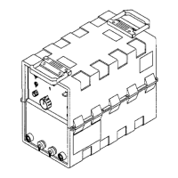
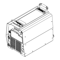
Illustrates the assembly of unit components with item numbers.
Lists detailed part numbers and descriptions for unit components.
Explains warranty coverage, terms, and exclusions.
Provides space for owner details and service contact information.
| Input Frequency | 50/60 Hz |
|---|---|
| Output Current Range (CC) | 5 - 450 A |
| Output Current Range (CV) | 10 - 450 A |
| Duty Cycle | 100% at 450 A |
| Input Voltage | 208/230/460 V |
| Input Phase | 3-Phase |
| Welding Processes | MIG (GMAW), Stick (SMAW), TIG (GTAW), Flux-Cored (FCAW) |