Do you have a question about the Miller Auto-Line XMT 350 CC and is the answer not in the manual?
Explains warning symbols used in the manual for hazard identification.
Details hazards associated with arc welding processes, including electrical shock and burns.
Explains safety symbols specific to CE products, detailing potential hazards.
Provides definitions for various symbols used in the manual, including process and control indicators.
Instructs on finding the serial and rating information on the unit's rear panel.
Directs users to the EULA and third-party software terms online.
Advises on the use and limitations of default weld parameters and user responsibility.
Details electrical and performance specifications like input power, output, and duty cycle.
Provides physical dimensions and weight of the welding unit.
Lists environmental operating conditions, including IP rating and temperature ranges.
Details operating and storage/transportation temperature ranges for the equipment.
Illustrates the minimum and maximum voltage and amperage output capabilities.
Explains duty cycle percentages and procedures for preventing and handling overheating.
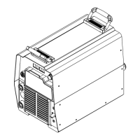
Provides guidelines for choosing a suitable and safe location for the welding unit.
Offers a guide for selecting appropriate weld cable sizes based on amperage and length.
Identifies the positive and negative weld output terminals on the unit.
Details the function and pinouts of the 14-pin remote receptacle.
Describes the optional receptacle and its protective circuit breakers.
Explains how to connect and operate the shielding gas system for TIG processes.
Provides recommendations for electrical service, including voltage, current, and conductor sizing.
Details the procedure for safely connecting single-phase input power to the unit.
Details the procedure for safely connecting three-phase input power to the unit.
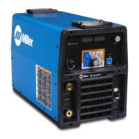
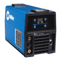
Identifies and explains the function of the controls on the front panel of the welding unit.
Describes how to set the mode switch for different welding processes and output controls.
Illustrates the standard connection setup for Gas Tungsten Arc Welding (GTAW).
Explains how to set up and operate the unit in Scratch Start TIG mode.
Details the setup and operation for Lift-Arc TIG welding, emphasizing arc initiation.
Covers the general TIG welding mode setup and operation requirements.
Shows the connection diagram for GMAW/FCAW with a remote wire feeder.
Explains the setup and operation for MIG welding, including arc control.
Illustrates connections for Pulsed MIG welding (GMAW-P) with a remote feeder.
Details the operation of the unit in Pulsed MIG mode, requiring an external pulsing device.
Shows the typical connection for a voltage-sensing feeder in GMAW/FCAW processes.
Explains the setup and operation for V-Sense Feeder welding mode.
Illustrates the standard connection setup for SMAW and Carbon Arc Cutting (CAC-A).
Details the setup and operation for Constant Current (CC) mode welding.
Explains the setup and operation for Stick welding, including Arc Control.
Describes the optional low OCV feature for Stick and Scratch Start TIG modes.
Explains how to configure remote control operation and meter display modes.
Outlines a schedule for checking, cleaning, and replacing parts for regular maintenance.
Provides instructions on how to clean the unit's interior by blowing out dust.
Lists and explains various help messages displayed by the unit indicating status or malfunctions.
Offers solutions for common operational problems and error conditions.
| Input Voltage | 208/230/460 V |
|---|---|
| Input Frequency | 50 / 60 Hz |
| Duty Cycle | 60% at 350 A |
| Input Phase | 1/3 |
| Rated Output | 350 A at 32 V, 60% duty cycle |
| Welding Processes | MIG, Flux-Cored, Stick, TIG |