Do you have a question about the Miller Invision 352 MPa Auto-Line and is the answer not in the manual?
Explains warning and notice symbols used in the manual.
Covers electric shock, DC voltage, and hot parts hazards during arc welding.
Details risks from welding fumes, gases, arc rays, fire, and explosion.
Addresses flying metal, gas accumulation, EMF, and noise hazards.
Covers cylinder safety, falling equipment, and other operational risks.
Details hazards related to installation, operation, and maintenance.
Emphasizes reading all labels and manuals before operating.
Discusses HF radiation, arc welding interference, and California Prop 65 warnings.
Lists key safety standards and provides guidelines for EMF exposure.
Explains common manufacturer safety symbols and their meanings.
Highlights key technologies like Auto-Line, LVCT, cooling systems, and synergic operation.
Details arc control features like inductance and SharpArc, and parameter settings.
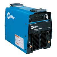
Locates serial number/rating label and mentions software licensing agreement.
Provides electrical specs, input power, output ratings, and default parameter info.
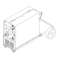
Lists physical dimensions, weight, and operating/storage temperature ranges.
Explains duty cycle, overheating indicators, and cooling procedures.
Describes output characteristics and influencing factors.
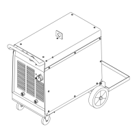
Guides on safe placement, movement, and airflow for the welding unit.
Covers selecting weld cable sizes and identifying output terminals.
Details the Remote 14 receptacle and optional 115V AC receptacle.
Provides detailed electrical service requirements for 1-phase and 3-phase power connections.
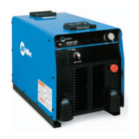
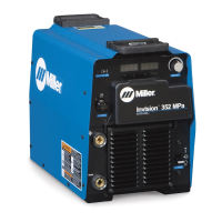
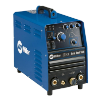
Identifies and explains front panel indicators, displays, and controls.
Describes how to access and navigate the machine's configuration menu.
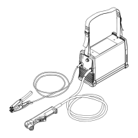
Illustrates standard connection setup for remote feeders in MIG, Pulsed MIG, and FCAW.
Explains setting up and operating MIG welding, including wire and gas selection.
Details setup for Pulsed MIG, including arc length and SharpArc adjustment.
Lists recommended wire types, gas types, and default inductance for MIG welding.
Provides wire and gas selection for Pulsed MIG welding processes.
Explains switching welding processes (MIG/Pulsed MIG) via remote feeder.
Outlines regular maintenance tasks like checking, cleaning, and replacing parts.
Provides instructions for cleaning dust and debris from the unit's interior.
Lists and explains help codes for status and malfunctions.
Offers solutions for common operational problems, no-output issues, and connectivity problems.
Presents the main circuit diagram for the welding power source.
Details Miller's limited warranty, coverage periods, and exclusions.
Lists conditions not covered and outlines exclusive remedies and disclaimers.
Space for recording ownership details for future reference.
Guides users on obtaining service, contacting distributors, and locating service agencies.
| Input Voltage | 208 - 575 V |
|---|---|
| Input Frequency | 50/60 Hz |
| Duty Cycle | 60% at 350 A |
| Auto-Line | Yes |
| Input Phase | 1- or 3-Phase |
| Rated Output | 350 A at 60% Duty Cycle |
| Output Current Range | 5 - 425 A |
| Welding Processes | MIG, Flux-Cored, DC TIG, Stick |
| Wire Diameter Range | 0.6-1.2 mm (0.023-0.045 in) |