Do you have a question about the Miller Welding and is the answer not in the manual?
General safety information, including warnings and precautions for equipment use.
Explanation of safety alert symbols and signal words used in the manual.
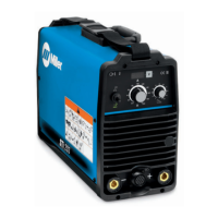
Overview of the robot PAW interface panel and its function.
Instructions for connecting the PAW interface panel to the computer interface.
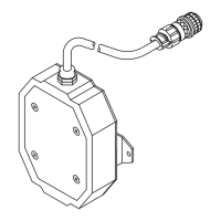
Procedures for assembling and installing the shock sensor unit onto the robot.
Guidance on installing shield sleeving for HF protection on the torch cable.
Steps for installing the torch and its cable onto the robot arm.
Instructions for connecting ground cables to the robot and associated equipment.
Steps for making internal connections for the torch cable to the welding console.
Connecting the PAW interface panel to the computer interface using specific plugs.
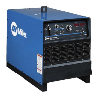
Connecting the PAW interface panel to the welding power source and console.
Connecting the computer interface to the external 115 VAC power supply.
Operation of the push button for gas flow and pilot arc initiation.
Connecting a remote switch for gas set and pilot arc start functions.
Procedure for setting up the plasma torch on the MRH2 robot.
Configuring welding power source parameters for PAW on C2 robot control.
Procedure for setting up the plasma torch on the MRV2 robot.
Marking the torch head assembly and sleeve for alignment adjustments.
Schematic diagram illustrating the overall Robot PAW system circuitry.
Schematic diagram of the Robot PAW interface panel circuitry.
Detailed wiring diagram for the Robot PAW interface panel.
Schematic diagram of the high-frequency filter circuit.
Wiring diagram for the high-frequency filter.
Explanation of high-frequency voltage and its role in starting the pilot arc.
Identifies sources of direct, conducted, and reradiated high-frequency radiation.
Guidance on correct installation to minimize high-frequency interference.
| Brand | Miller |
|---|---|
| Model | Welding |
| Category | Welding System |
| Language | English |