
D
Diane ButlerJul 27, 2025
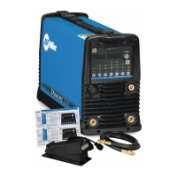
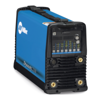
How to maintain coolant level in Miller Dynasty 280 Welding System?
- RrosarioalyssaJul 27, 2025
To maintain the coolant level in your Miller Welding System, regularly check it and top it off with distilled or deionized water as needed.