. A complete Parts List is available at www.MillerWelds.com
OM-253086 Page 19
SECTION 5 − INSTALLATION
! Special installation may be
required where gasoline or
volatile liquids are present −
see NEC Article 511 or CEC
Section 20.
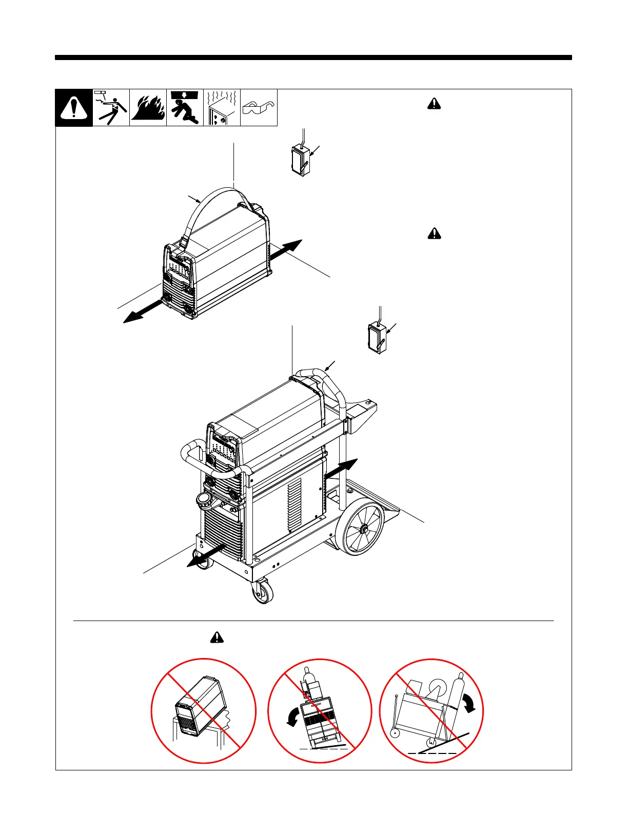
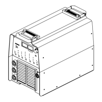
1 Carry Strap
Use strap to carry power source
only. Do not use to lift power source
when attached to cart/cooler.
2 Lift Handle
Use lift handle to move and lift weld-
er/cart/cooler.
! Do not use lift handle to lift
unit when gas cylinder and
accessories
are connected.
3 Line Disconnect Device
Locate unit near correct input
power supply.
! Do not move or operate unit where it could tip.
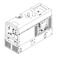
5-1. Selecting a Location
loc_dynasty
2018-08
Movement, Location, and Airflow
3
18 in. (460 mm)
18 in. (460 mm)
1
2
3
18 in. (460 mm)
18 in. (460 mm)