Do you have a question about the Miller Trailblazer 280 NT and is the answer not in the manual?
Explains hazard symbols used in the manual.
Details potential hazards associated with arc welding processes.
Outlines risks and safety measures related to the engine.
Covers symbols for installation, operation, and maintenance procedures.
Lists key safety standards and regulations relevant to welding.
Provides information on electromagnetic fields and their potential effects.
Defines symbols used throughout the manual for clarity.
Details technical specifications for welding, power output, and engine.
Provides physical dimensions, weight, and operating angle limits.
Illustrates fuel usage based on welding output and engine speed.
Shows the relationship between AC power output and voltage/amperage.
Explains the percentage of time the unit can operate at rated load without overheating.
Displays the output capabilities in terms of voltage and amperage for different modes.
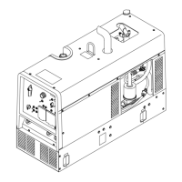
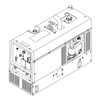
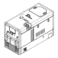
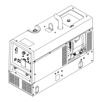
Instructions for physically setting up and positioning the welding generator.
Essential checks and fluid level verification before starting the engine.
Steps for preparing and installing a dry charge battery.
Guidance on correctly connecting the battery terminals.
Steps for properly installing the exhaust pipe for engine ventilation.
Instructions for connecting welding cables to the output terminals.
Recommendations for choosing appropriate weld cable sizes based on current and length.
Details the functions and pinouts of the Remote 14 receptacle.
Steps for adjusting the MIG weld puddle for desired wet-out or stiffness.
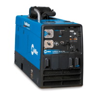
Description and function of all controls located on the front panel.
How to use optional remote controls for amperage and voltage adjustment.
Explains the auxiliary power outlets and their associated circuit breakers.
Details on additional optional auxiliary power outlets available.
Scheduled maintenance tasks and their recommended intervals.
Information typically found on the unit's maintenance label.
Procedures for cleaning and maintaining the air cleaner element.
Instructions for inspecting and servicing the optional spark arrestor.
Steps for performing routine oil and filter changes for the engine.
Guide on adjusting engine idle and weld/power speeds.
Explanation of the unit's overload protection mechanisms and circuit breakers.
Guide to diagnosing and resolving common welding, auxiliary power, and engine issues.
Guidance on choosing auxiliary equipment compatible with the generator.
Procedures for properly grounding the generator when mounted on a vehicle.
Instructions for grounding the generator when connecting to building electrical systems.
Explains how to calculate the power requirements of various equipment.
Tables showing power needs for different types of industrial motors.
Tables detailing power needs for farm and home equipment.
Tables listing power requirements for common contractor tools and equipment.
Explains how to calculate the starting amperage for single-phase induction motors.
Guidelines on managing generator output and starting loads.
| Max Output | 280 A |
|---|---|
| Welding Amperage Range | 20 - 280 A |
| Output Range | 20 - 280 A |
| Fuel Type | Gasoline |
| Type | Engine Driven Welding Generator |
| Maximum Open Circuit Voltage | 80V |
| Welding Processes | Stick, TIG |
| Input Voltage | N/A (Engine Driven) |
| Input Current | N/A (Engine Driven) |