M
Mr. Sean GibsonSep 15, 2025
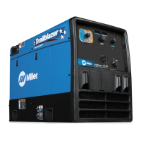
What to do if the engine stopped during normal operation of my Miller Trailblazer 325 Diesel Welding System?
- JJim RomeroSep 16, 2025
If the engine stops during normal operation, first check the fuel level and front panel fault indicators. Next, check the oil level; the engine will not start if oil pressure is too low. Also, check the coolant level and fan belt; the engine stops if the engine temperature is too high. If these steps don't resolve the issue, have a Factory Authorized Service Agent check the low oil pressure shutdown switch S3 and engine temperature switch S4.