EasyManua.ls Logo

Miller Trailblazer 302 Diesel User Manual

Miller Trailblazer 302 Diesel
68 pages
To Next Page IconTo Next Page
Page #1 background imageLoading...
Page #1 background image
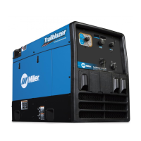
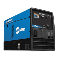
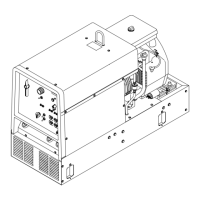
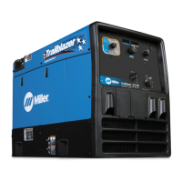
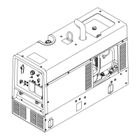
Trailblazer 302 Diesel
Processes
Description
R
AC/DC TIG (GTAW) Welding
Stick (SMAW) Welding
MIG (GMAW) Welding
Flux Cored (FCAW) Welding
Engine Driven Welding Generator
OM-217 454S
201105
File: Engine Drive
Visit our website at
www.MillerWelds.com

Table of Contents

Questions and Answers:

Miller Trailblazer 302 Diesel Specifications

General IconGeneral
TypeEngine-Driven Welding Generator
Fuel TypeDiesel
Rated Output300 A at 32 VDC, 100% Duty Cycle
EngineKubota D722
Generator Power10, 000 Watts
Welding ProcessesStick (SMAW), TIG (GTAW), MIG (GMAW), Flux-Cored (FCAW)
Dimensions20.5 in
Welding Amperage Range30-300A
Fuel Tank Capacity12 gallons

Summary

OWNER'S MANUAL

Trailblazer 302 Diesel

Model name and designation of the welding generator.

From Miller to You

SECTION 1 – SAFETY PRECAUTIONS

Symbol Usage

Explanation of safety symbols used throughout the manual to identify hazards.

Arc Welding Hazards

Details potential hazards associated with arc welding processes and provides safety guidelines.

Engine Hazards

Highlights dangers related to the engine, including battery explosion, fuel, and moving parts.

Hydraulic Hazards

Covers risks associated with hydraulic equipment, fluid, and moving parts.

California Proposition 65 Warnings

Principal Safety Standards

SECTION 3 – DEFINITIONS

Symbol Definitions

Defines various symbols used in the manual, including operational and safety indicators.

SECTION 4 – SPECIFICATIONS

Weld, Power, and Engine Specifications

Provides detailed technical specifications for welding output, power ratings, and engine.

SECTION 5 – INSTALLATION

Installing Welding Generator

Guidance on how to properly position and mount the welding generator unit.

Grounding Generator To Truck Or Trailer Frame

Instructions for safely grounding the generator frame to a vehicle for electrical safety.

Connecting the Battery

Steps for correctly connecting the generator's battery, including polarity.

SECTION 6 – OPERATING THE WELDING GENERATOR

Engine Control Switches

Details the function and operation of engine control switches for starting, stopping, and speed.

Weld Output Controls

Explains the controls for adjusting weld voltage, amperage, and selecting welding processes.

Process/Contactor Switch

Describes how to use the switch to select welding processes and control weld output.

Stick Start Procedure – Scratch Start Technique

Provides step-by-step instructions for initiating a stick welding arc using the scratch start method.

Lift-Arc™ TIG With Auto-Crater™ And Auto-Stop

Remote Amperage Control

SECTION 7 – OPERATING AUXILIARY EQUIPMENT

Generator Power Receptacles

Details the types and ratings of power receptacles available for auxiliary equipment.

Wiring Optional 240 Volt Plug

Instructions and diagrams for wiring a 240-volt plug for auxiliary power connections.

SECTION 8 – MAINTENANCE AND TROUBLESHOOTING

Routine Maintenance

Schedule and procedures for regular maintenance tasks based on operating hours.

Servicing Air Cleaner

Steps for cleaning or replacing the engine's air filter element.

Maintenance Label And Engine Maintenance Activities

Information on engine oil, fuel, coolant, and related maintenance activities.

TRAILBLAZER KUBOTA D722 ENGINE

Specific engine maintenance details, including fluid capacities and service intervals.

Adjusting Engine Speed

Overload Protection

Troubleshooting Tables

SECTION 9 – PARTS LIST

Recommended Spare Parts

List of essential spare parts recommended for maintenance and replacement.

SECTION 10 – ELECTRICAL DIAGRAMS

Circuit Diagram For Welding Generator

Detailed electrical schematic showing the generator's wiring and components.

SECTION 11 – RUN-IN AND WETSTACKING

Run-In And Wetstacking

Information regarding engine run-in procedures and the phenomenon of wetstacking.

SECTION 12 – PERFORMANCE DATA

Fuel Consumption Curves

Graphs illustrating fuel consumption rates based on welding load and auxiliary power usage.

Generator Power Curve

Chart showing available AC power output in amperes at different voltages.

Duty Cycle

Explanation and graph detailing the unit's welding duty cycle capabilities.

Stick Mode Volt-Ampere Curves

Volt-ampere characteristics for Stick welding modes (CC/DC and CC/AC).

TIG Mode Volt-Ampere Curves

MIG Mode Volt-Ampere Curve

SECTION 13 – GENERATOR POWER GUIDELINES

Selecting Equipment

Guidance on choosing appropriate auxiliary equipment and understanding power requirements.

Grounding Generator To Truck Or Trailer Frame

Instructions for grounding the generator when mounted on vehicles.

How Much Power Does Equipment Require?

Information on calculating power needs for various electrical equipment.

Power Required To Start Motor

Typical Connections To Supply Standby Power

Selecting Extension Cord

Related product manuals