Do you have a question about the Miller Trailblazer 251 and is the answer not in the manual?
Explains the meaning of symbols used in the manual for safety warnings.
Details hazards associated with arc welding processes and protective measures.
Outlines potential dangers related to the engine, fuel, and exhaust systems.
Covers symbols for specific operational and maintenance hazards and precautions.
Lists key safety standards and codes relevant to welding equipment.
Discusses electromagnetic field effects and how to minimize exposure.
Provides a glossary of symbols used in the manual for clarity and understanding.
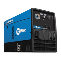
Details technical specifications for welding output, auxiliary power, and engine.
Lists physical dimensions, weight, and safe operating angles for the unit.
Provides data on the unit's fuel consumption rates under various operating conditions.
Illustrates the available auxiliary power output at different amperage levels.
Explains duty cycle percentages and their impact on unit performance and warranty.
Graphic representation of voltage and amperage output capabilities across different modes.
Step-by-step guide for physically installing the welding generator unit.
Essential checks to perform on the engine before starting the unit.
Instructions for properly connecting the unit's battery for operation.
Guidance on connecting cables to the correct output terminals for welding.
Table for choosing appropriate weld cable sizes based on amperage and length.
Details the function and pin configuration of the Remote 14 receptacle.
Procedures for fine-tuning MIG welding puddle characteristics for optimal welds.
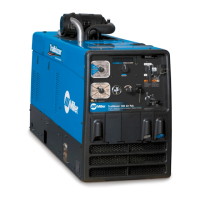
Explanation of the function of each control on the generator's front panel.
How to connect and use optional remote controls for amperage and voltage adjustment.
Information on using auxiliary power outlets and understanding circuit breakers.
Schedule and procedures for regular maintenance tasks to ensure optimal performance.
Details found on the engine's maintenance label for quick reference.
Step-by-step guide for cleaning and maintaining the air cleaner element.
Instructions for inspecting and cleaning the optional spark arrestor.
Procedures for replacing engine oil, oil filter, and fuel filter.
How to adjust engine idle and weld/power speeds for proper operation.
Explanation of overload protection features and circuit breaker reset procedures.
Guidance for diagnosing and resolving common welding and engine operational issues.
Advice on choosing auxiliary equipment compatible with the generator's output.
Instructions for properly grounding the generator when mounted on a vehicle frame.
Guidance on grounding the generator when connecting to building electrical systems.
Explains how to calculate power requirements for connected equipment.
Table listing typical power requirements for various industrial motors.
Table listing typical power requirements for farm and home equipment.
Table listing typical power requirements for contractor equipment.
Explains how to determine the starting amperage needed for motors.
Guidance on generator output limits and starting motor loads.
Diagrams and instructions for connecting the generator for standby power.
Tables and guidelines for selecting appropriate extension cords based on load and length.
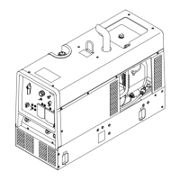
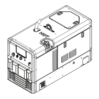
Exploded view of the main assembly with numbered parts.
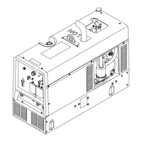
Detailed view of the front panel components and their part numbers.
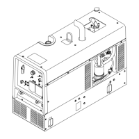
Exploded view of the generator assembly and its components.
| Frequency | 60 Hz |
|---|---|
| Power Factor | 0.95 |
| Efficiency | 85% |
| Fuel Type | Gasoline |
| Input Phase | Single/Three |
| Engine | Kohler CH |
| Fuel Tank Capacity | 12 gallons |
| Fuel Consumption | 1.5 gal/hr |
| Welding Processes | Stick, MIG, TIG |
| Welding Amperage Range | 40 - 250 A |