EasyManua.ls Logo

Miller Spectrum 625 X-TREME - User Manual

Miller Spectrum 625 X-TREME
52 pages
Print Icon
To Next Page IconTo Next Page
Loading...
Processes
Description
Air Plasma Cutting
and Gouging
Air Plasma Cutter
OM-264 267C 201409
Spectrum 625 X-TREME
And XT40 Torch
R
File: Plasma Cutters
Visit our website at
www.MillerWelds.com

Table of Contents

Questions and Answers

  • H
    Heather HumphreySep 10, 2025
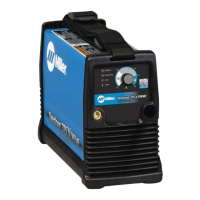
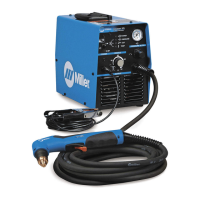
    What to do if pilot arc is working but there is no cutting output on Miller Spectrum 625 X-TREME Welding System?
    • R
      rogersjeremySep 10, 2025
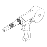
      If the pilot arc is working but there's no cutting output, ensure the work clamp is connected. Additionally, clean or replace worn consumables as necessary.
  • M
    Melanie DelgadoAug 22, 2025
    Why is the Pressure status light on for Miller Spectrum 625 X-TREME Welding System?
    • D
      Daniel HuffAug 22, 2025
      If the pressure status light is on, check for sufficient gas/air supply pressure. Inspect the air filter and replace it if it's dirty. Also, check the air lines for leaks.
  • S
    Steven HoltAug 25, 2025
    Why is the Cup status light on for Miller Spectrum 625 X-TREME?
    • J
      Joseph SmithAug 25, 2025
      If the cup status light is on, check the torch shield cup and reset the power switch.
  • G
    garciaallisonAug 26, 2025
    What causes short tip life on Miller Welding System?
    • B
      Brianna GravesAug 26, 2025
      To address short tip life, check and clean the drag shield of any slag, particles, and debris. Also, check the input air pressure.
  • J
    Jared BerryAug 27, 2025
    What to do if my Miller Spectrum 625 X-TREME has pilot arc working but no cutting output?
    • A
      amy29Aug 28, 2025
      If your Miller Welding System's pilot arc is working but there's no cutting output, ensure the work clamp is properly connected. Additionally, inspect the consumables for wear and clean or replace them as needed.
  • S
    smithandreAug 29, 2025
    What to do if the pressure status light is on in my Miller Welding System?
    • M
      michael31Aug 29, 2025
      If the pressure status light is illuminated on your Miller Welding System, you should: * Check for sufficient gas/air supply pressure. * Inspect the air filter for dirt and replace it if necessary, following the manufacturer’s instructions. * Check air lines for leaks.
  • S
    Steven PerezSep 18, 2025
    What to do if there is no cutting output, power light off, status lights off, and fan motor does not run on Miller Welding System?
    • J
      Jennifer TurnerSep 18, 2025
      If there is no cutting output, the power light is off, status lights are off, and the fan motor doesn't run, place the power switch in the On position. Also, place the line disconnect device in the On position. Check the line fuses and replace them if needed, or reset the circuit breakers.
  • R
    Richard Nichols DDSSep 12, 2025
    What to do if Pressure status light flashes on Miller Spectrum 625 X-TREME?
    • R
      Ruben BrownSep 12, 2025
      If the pressure status light flashes, it indicates the unit momentarily lost pressure while cutting. Check the air line for leaks.
  • J
    Jennifer AdamsSep 8, 2025
    What to do if Trouble lights are on and unit has no cutting output on Miller Spectrum 625 X-TREME?
    • R
      Richard VillarrealSep 8, 2025
      If the trouble lights are on and the unit has no cutting output, check the torch consumables and ensure there is gas/air flow at the torch. Verify the air supply connection and pressure to the unit and torch. Try resetting the unit power switch.
  • Z
    zjoyceSep 5, 2025
    What to do if arc goes out while cutting with Miller Spectrum 625 X-TREME Welding System?
    • F
      Francisco WilliamsSep 5, 2025
      If the arc goes out while cutting, make sure the work clamp is securely attached to the workpiece. Ensure the tip is on or near the workpiece [1/16 in. (1.6 mm) to 1/8 in. (3.2 mm)]. Clean or replace torch consumables if necessary.

Summary

Section 1 - Safety Precautions - Read Before Using

1-1. Symbol Usage

Explains symbols used for warnings and instructions within the manual.

1-2. Plasma Arc Cutting Hazards

Details hazards associated with plasma arc cutting, including fire, electric shock, and fumes.

1-3. Installation, Operation, And Maintenance Symbols

Covers additional safety symbols for installation, operation, and maintenance procedures.

1-4. California Proposition 65 Warnings

Provides warnings related to chemicals in the product that may cause birth defects or cancer.

1-5. Principal Safety Standards

Lists key safety standards and organizations relevant to welding and cutting equipment.

1-6. EMF Information

Explains electromagnetic fields (EMF) and their potential interference with medical implants.

Section 2 - Safety Guidelines - Read Before Use

2-1. Symbol Significance

Explains the meaning of safety symbols used in the manual.

2-2. Plasma Arc Cutting Hazards

Details hazards related to plasma arc cutting, covering fire, electric shock, and fumes.

2-3. Additional Installation, Operation, And Maintenance Hazards

Covers additional hazards related to installation, operation, and maintenance.

2-4. California Proposition 65 Warnings

Warnings about chemicals known to cause birth defects or cancer in California.

2-5. Principal Safety Standards

Lists principal safety standards relevant to welding and cutting.

2-6. CEM Information

Information on electromagnetic fields (CEM) and medical implants.

Section 3 - Definitions

3-1. Additional Safety Symbols And Definitions

Defines additional safety symbols, some specific to CE products.

3-2. Miscellaneous Symbols And Definitions

Provides definitions for various miscellaneous symbols used in the manual.

Section 4 - Specifications

4-1. Serial Number And Rating Label Location

Indicates where to find the serial number and rating label on the unit.

4-2. Unit Specifications

Details electrical specifications, power supply, and output characteristics of the unit.

4-3. Torch Dimensions And Weight

Provides physical dimensions and weight specifications for the XT40 torch.

4-4. Duty Cycle And Overheating

Explains duty cycle percentages and the causes/effects of overheating.

4-5. Power Source Dimensions And Weight

Lists the physical dimensions and weight of the power source unit.

4-6. Environmental Specifications

Details environmental specifications including IP rating and operating temperature range.

Section 5 - Installation

5-1. Selecting A Location

Guidelines for choosing a proper and safe location for the equipment.

5-2. Connecting Gas;Air Supply

Instructions on connecting the gas or air supply to the unit.

5-3. Connecting And Disconnecting Torch

Procedures for connecting and disconnecting the plasma torch.

5-4. Connecting And Disconnecting Work Cable

Procedures for connecting and disconnecting the work cable.

5-5. Connecting Work Clamp

Details on how to properly connect the work clamp to the workpiece.

5-6. Electrical Service Guide

Recommendations for electrical service, including voltage, amperage, and conductor size.

5-7. Extension Cord Data

Provides guidance on selecting extension cords based on voltage and length.

5-8. Multi-Voltage Plug Adapter (MVP) Connection

Instructions for using multi-voltage plug adapters for different power supply configurations.

5-9. Connecting 120 Volt Input Power

Steps for connecting the unit to a 120-volt AC input power source.

5-10. Connecting 1-Phase Input Power For 240 VAC

Instructions for connecting the unit to a 240-volt AC single-phase input power source.

Section 6 - Operation

6-1. Standard Front Panel Controls

Describes standard front panel controls for operating the unit.

6-2. Automation Front Panel Controls

Describes automation front panel controls for operating the unit.

6-3. Cutting Speed

Provides recommended cutting speeds for various materials and thicknesses.

6-4. Safety Features and Practices

Covers trigger safety lock and best practices for plasma cutting.

6-5. Operation Sequences

Provides step-by-step sequences for cutting, gouging, and piercing operations.

Section 7 - Mechanized Operation

7-1. XT40 M Mounting Position

Instructions on how to mount the XT40M torch for mechanized use.

7-2. Remote Control Receptacle

Identifies the remote control receptacle and its purpose for arc start inputs.

7-3. Remote Control Cable Functions

Describes the functions of different wires within the remote control cable set.

7-4. Remote Control Cable Connection

Illustrates how to connect the remote control cable to the unit's receptacle.

Section 8 - Maintenance & Troubleshooting

8-1. Routine Maintenance

Outlines regular maintenance tasks to keep the equipment in good working order.

8-2. Wrapper Removal

Step-by-step guide for safely removing the unit's outer wrapper for access.

8-3. Filter Element Check;Replacement

Instructions for inspecting and replacing the air filter element.

8-4. Shield Cup Shutdown System Check

Procedure for checking the shield cup shutdown system for proper function.

8-5. Torch Consumables Check;Replacement

Guide for inspecting and replacing torch consumables like the tip and electrode.

8-6. Status;Trouble Lights

Explains the meaning of various status and trouble lights on the unit.

8-7. Power Source Troubleshooting

Provides solutions for common problems related to the power source operation.

8-8. Torch Troubleshooting

Offers troubleshooting steps for issues specific to the plasma torch.

Section 9 - Electrical Diagram

Section 10 - Parts List

10-1. Recommended Spare Parts

Lists recommended spare parts for the equipment, including part numbers.

Warranty

Owners Record

For Service

Miller Spectrum 625 X-TREME Specifications

General IconGeneral
Output Range20 - 50 A
ProcessPlasma Cutting
Amperage Range20 - 50 A
Maximum Open-Circuit Voltage300 VDC
CNC InterfaceYes
Rated Output50 A / 60% Duty Cycle
Duty Cycle60%

Related product manuals