EasyManua.ls Logo

Miller Spoolmatic - Pro 30A - User Manual

Miller Spoolmatic - Pro 30A
36 pages
Print Icon
To Next Page IconTo Next Page
Loading...
Spoolmatic - Pro
15A And 30A
Processes
OM-264 713B
201408
MIG (GMAW) Welding
File: MIG (GMAW)
Visit our website at
www.MillerWelds.com
Description
Semi-Automatic, Air-Cooled,
MIG (GMAW) Welding Gun
R

Questions and Answers

  • M
    margaret23Aug 1, 2025
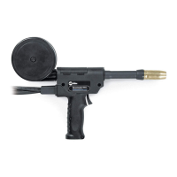
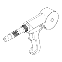
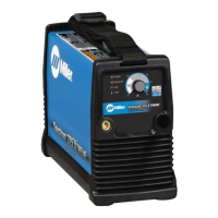
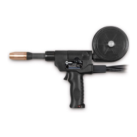
    How to fix erratic wire feed on Miller Spoolmatic - Pro 30A Welding System?
    • J
      josephwebsterAug 1, 2025
      To address erratic wire feed in your Miller Welding System, you should: * Check and correct the drive roll pressure. * Clean or replace the drive roll. * Decrease spool brake pressure.
  • C
    Crystal GoodwinAug 6, 2025
    What to do if Miller Welding System has erratic weld output?
    • F
      Felicia EdwardsAug 7, 2025
      If your Miller Welding System is producing erratic weld output, the suggested solution is to tighten and clean all connections.
  • A
    Aaron SchmidtAug 13, 2025
    How to troubleshoot no weld output on Miller Spoolmatic - Pro 30A Welding System?
    • A
      Alexis WebbAug 13, 2025
      If your Miller Welding System has no weld output and the gun/feeder isn't working, ensure the weld control plug is securely in the 115 volts AC receptacle. Also, check that the Power switch on the welding power source is in the On position.
  • D
    Dawn MartinezAug 19, 2025
    Why is welding wire not energized on Miller Spoolmatic - Pro 30A?
    • S
      Sarah PrattAug 19, 2025
      If the wire feeds and shielding gas flows, but the welding wire is not energized on your Miller Welding System, ensure the control cable leads are secure in the weld control.
  • G
    gjenkinsAug 26, 2025
    What to do if Miller Spoolmatic - Pro 30A Welding System trigger doesn't energize weld control?
    • S
      Stephanie VelasquezAug 26, 2025
      If pressing the gun/feeder trigger does not energize the weld control, and the welding wire is not energized while the shielding gas does not flow on your Miller Welding System, make sure the plug from the gun/feeder trigger cord is securely inserted into the 10-socket receptacle on the weld control.

Summary

Safety Precautions

Symbol Usage

Explains hazard symbols used in the manual to indicate potential dangers.

Arc Welding Hazards

Details various dangers associated with arc welding processes, including electric shock, fumes, and gases.

Proposition 65 Warnings

Lists chemical warnings mandated for California residents regarding cancer and birth defects.

Principal Safety Standards

References key industry safety standards and organizations relevant to welding and cutting.

EMF Information

Discusses electromagnetic fields and their potential impact on medical implants, with safety measures.

Definitions

Additional Safety Symbols And Definitions

Explains additional safety symbols, particularly those found on CE products.

Miscellaneous Symbols And Definitions

Defines various technical symbols used in the manual, such as voltage, current, and duty cycle.

Specifications

Gun Specifications

Details technical specifications for the welding gun, including wire range, cooling, and dimensions.

Duty Cycle And Overheating

Explains duty cycle calculation and potential consequences of overheating the unit.

Installation

Connecting To 24 Volt Weld Control

Step-by-step guide for connecting the welding gun to a 24V weld control system.

Maintenance & Troubleshooting

Replacing Canister Inlet Guide

Instructions for replacing the canister inlet guide on the welding gun.

Replacing Spool Canister

Procedure for removing and installing a new spool canister.

Replacing Head Tube Liner

Instructions for replacing the head tube liner in the welding gun.

Removing Diffuser In Air And Water-Cooled Pistol-Grip Guns

Steps to remove and replace the diffuser in air and water-cooled gun assemblies.

Changing Gun Contact Tip

Guide for safely replacing the gun contact tip.

Gun Drive Assembly Maintenance

Procedures for maintaining the gun drive assembly, including drive rolls.

Troubleshooting

Lists common problems encountered with the welding gun and provides remedies.

Electrical Diagrams

Circuit Diagram For Spoolmatic Pro Gun

Illustrates the electrical circuit diagram for the Spoolmatic Pro Gun.

Parts List

Exploded View Of Spoolmatic Pro Gun

Visual representation of gun components with part numbers for identification.

Parts List Including Consumables

Consumables Flowchart

Visual guide to available consumables such as nozzles, tips, and diffusers for the gun.

Warranty

Limited Warranty Terms

Outlines the terms and conditions of the Miller limited warranty for equipment.

Owners Record

Service Information

Details how to obtain service, contact distributors, and record equipment information.

Miller Spoolmatic - Pro 30A Specifications

General IconGeneral
Input Voltage24 VAC
Wire Diameter Range0.030 - .047 in (0.8 - 1.2 mm)
Duty Cycle60% at 300 A
Length15 ft (4.57 m)
Compatible Power SourcesMiller power sources
Drive Roll TypeDual

Related product manuals