

J
Justin MartinezAug 17, 2025
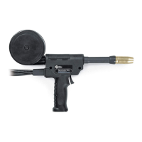
What to do if I have erratic weld output on my Miller Spoolmatic 30A?
- Ddana08Aug 17, 2025
If you are experiencing erratic weld output with your Miller Welding System, make sure to tighten and clean all connections.
What to do if I have erratic weld output on my Miller Spoolmatic 30A?
If you are experiencing erratic weld output with your Miller Welding System, make sure to tighten and clean all connections.
How to troubleshoot no weld output on my Miller Spoolmatic 30A Welding System?
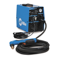
If your Miller Welding System has no weld output and the gun/feeder isn't working, ensure the weld control plug is securely in the 115 volts AC receptacle (refer to the weld control Owner’s Manual) and the power switch on the welding power source is in the On position (refer to the welding power source Owner’s Manual).
How to fix erratic wire feed on Miller Welding Accessories?
To address erratic wire feed or lack of wire speed control, try the following: change to the correct size contact tip or liner, and clear any obstruction in the contact tip or liner. Readjust the drive roll pressure and change to the correct size drive roll. Clean or replace a dirty or worn drive roll, and readjust the spool brake pressure. Check the resistance and connections of the Wire Speed control R4, replacing it if necessary. Also, check the motor B2, replacing it if needed, and check control cords for continuity, repairing or replacing if necessary.
What to do if Miller Welding Accessories wire burns back into contact tip?
If the wire feeds but burns back into the contact tip, try these solutions: readjust the voltage setting on the welding power source and repair the ground cable connection. You can also replace a worn or damaged contact tip, clean or replace the current pickup tab and readjust the wire speed ramp up setting.
What to do if the labels on my Miller Other are damaged or unreadable?
If the labels on your Miller Other are damaged or unreadable, replace them.
What should I do if the cords on my Miller Other are damaged?
If the cords on your Miller Other are damaged, you should replace them.
What to do if the Miller Welding Accessories motor doesn't run?
If the motor does not run when you press the gun trigger, and the weld control or welding power source isn't energized, check the connection of the 10 pin plug PLG2 to the weld control or welding power source and repair if necessary. Also, verify the continuity of the gun trigger switch and leads, repairing or replacing if needed. Inspect the control cords for continuity, repairing or replacing them if necessary. Finally, readjust the drive roll pressure.
Why is the weld output erratic on my Miller Welding Accessories?
If you're experiencing erratic weld output, replace any worn or damaged contact tips and repair any loose or incorrect welding connections. Also, check the control cords for continuity, repairing or replacing them if necessary.
What to do if Miller Welding Accessories wire feeds but is not energized?
If the wire feeds, but the welding wire is not energized, check the switch positions on the welding power source. Also, check the connection of the 10 pin plug PLG2 to the weld control, repairing if necessary, and check the control cords for continuity, repairing or replacing if necessary.
How to stop continuous gas flow in Miller Welding Accessories?
To stop continuous gas flow, reduce the regulator pressure to below 50 PSI. Check, repair, or replace the valve cap, and check, repair, or replace any misaligned or missing spring. Also, check the orifice in the gun housing, replacing it if necessary.
Explains the meaning of warning symbols used in the manual for safety.
Details potential dangers associated with arc welding processes.
Describes additional symbols used for installation, operation, and maintenance procedures.
Lists principal safety standards relevant to welding equipment operation and safety.
Provides information on electromagnetic fields and their potential effects during welding.
Explains the manufacturer's rating label found on CE-certified products.
Defines various symbols and terms used within the manual.
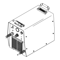
Details the technical specifications of the welding equipment.
Provides instructions on how to remove the top cover of the equipment.
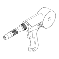
Guides on how to adjust the position of the contact tip for optimal welding.
Instructions for installing the wire spool and threading the welding wire.
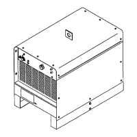
Steps for rotating the canister to the desired position.
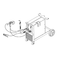
How to connect the welding equipment to a 24 Volt weld control system.
How to connect the welding equipment to a 115 Volt weld control system.
Procedures for installing the shielding gas supply system.
Guidance on adjusting the drive roll and spool brake pressure.
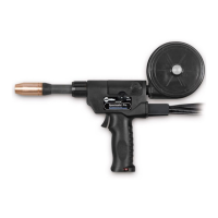
Overview and explanation of the equipment's controls.
Instructions on how to use and manage the shielding gas during operation.
Outlines regular maintenance tasks to ensure proper equipment function.
Step-by-step guide for replacing the contact tip and liner.
Procedures for maintaining the gun drive assembly.
Instructions for replacing the canister inlet guide.
Steps for replacing the spool canister.
Guidance on how to replace the contact tip adapter.
Provides solutions for common problems encountered during operation.
| Brand | Miller |
|---|---|
| Model | Spoolmatic 30A |
| Category | Welding System |
| Language | English |