M
michaelsmithSep 23, 2025
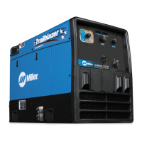
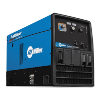
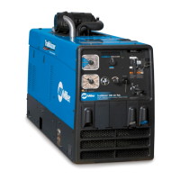
How to prevent tungsten electrode oxidizing on a Miller Trailblazer 275?
- KkelleycourtneySep 23, 2025
If the tungsten electrode is oxidizing and not remaining bright after the conclusion of a weld with your Miller Welding System, shield the weld zone from drafts. Increase the postflow time. Check and tighten all gas fittings. Ensure that you properly prepare the tungsten.