
M
Mary ChandlerSep 23, 2025
What to do if Miller Welding System engine uses oil during run-in period?
- TTrevor SullivanSep 23, 2025
If the engine of your Miller Welding System uses oil during the run-in period and wetstacking occurs, dry the engine.
What to do if Miller Welding System engine uses oil during run-in period?
If the engine of your Miller Welding System uses oil during the run-in period and wetstacking occurs, dry the engine.
What to do if my Miller Trailblazer 300D NT Welding System engine does not start?
If the engine of your Miller Welding System does not start, consider the following: * Check the fuel level. * Open the fuel valve. * Service the primary and secondary fuel filters. * Check the battery and replace it if necessary. * Check the engine charging system according to the engine manual. * Bleed air from the fuel system according to the engine manual. * Consult the engine manual for further assistance.
Why Miller Trailblazer 300D NT Welding System has low weld output and how to fix it?
If your Miller Welding System has low weld output, try these solutions: * Check the control settings. * Place the Remote Amperage/Voltage switch in the Panel position, or move the switch to the Remote 14 position and connect the remote amperage/voltage control to the Remote 14 receptacle RC1. * Check and clean the air cleaner as necessary. * Check the engine speed, and adjust if necessary. * If the issue continues, have a Factory Authorized Service Agent check the brushes, slip rings, and field current control board PC2. * Refer to the engine manual for additional guidance.
How to fix erratic weld output on Miller Trailblazer 300D NT?
If the weld output of your Miller Welding System is erratic, you can take the following steps: * Check the control settings. * Clean and tighten connections both inside and outside the unit. * Check and secure lead connections to the A/V control. * Ensure the connection to the work piece is clean and tight. * Remove excessive coils from weld cables. * Use dry, properly stored electrodes. * Check the engine speed, and adjust if necessary. * If the problem persists, have a Factory Authorized Service Agent check the brushes, slip rings, and field current control board PC2.
What to do if Miller Welding System engine stopped during normal operation?
If your Miller Welding System engine stopped during normal operation, you should: * Check the fuel level. * Open the fuel valve. * Check the oil level, as the engine stops if oil pressure is too low. * Check the coolant level and fan belt, as the engine stops if engine temperature is too high. * Bleed air from the fuel system according to the engine manual. * If problems continue, have a Factory Authorized Service Agent check the low oil pressure shutdown switch S5 and engine temperature switch S7.
What to do if there is no power output at Remote 14 receptacle RC1 on Miller Trailblazer 300D NT?
If there is no power output at the Remote 14 receptacle RC1 of your Miller Welding System, reset circuit breaker CB1 and/or CB2.
Why remote contactor control does not activate contactor on Miller Welding System?
If the remote contactor control does not activate the contactor on your Miller Welding System: * Place the Output (Contactor) switch in the Remote 14 position. * Check and tighten connections to the Remote 14 receptacle RC1.
How to fix wandering arc and poor arc direction control on Miller Trailblazer 300D NT Welding System?
If you are experiencing a wandering arc and poor control of arc direction with your Miller Welding System: * Reduce the gas flow rate. * Select the proper size tungsten and properly prepare it.
Why Miller Trailblazer 300D NT engine does not return to idle speed?
If the engine of your Miller Welding System does not return to idle speed, you can try: * Ensuring the Engine Control switch S2 is in the Run/Idle position. * Removing all weld and auxiliary power loads. * Turning off any remote device connected to the Remote 14 receptacle RC1. * Checking for obstructed movement of the solenoid linkage. * Checking fuse F5, and replacing it if open. * If the problem continues, have a Factory Authorized Service Agent check the idle module PC1 and current transformer CT1.
What to do if Miller Trailblazer 300D NT Welding System engine does not stop?
If the engine of your Miller Welding System does not stop: * Stop the engine by closing the fuel valve. * Adjust the shutdown solenoid.
Explains the meaning of various safety symbols used in the manual to highlight hazards.
Details hazards associated with arc welding, including electric shock, arc rays, and fumes.
Covers hazards related to the engine, such as fuel fires, steam burns, and exhaust gases.
Highlights further safety symbols for installation, operation, and maintenance of the equipment.
Lists key safety standards and codes relevant to welding and equipment operation.
Provides information on electromagnetic fields and their potential effects, including on pacemakers.
Defines symbols used throughout the manual for operational and safety guidance.
Details specifications for welding modes, power output, and engine parameters of the generator.
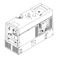
Lists physical dimensions, weight, and operating angle limits for the welding generator.
Presents a graphical representation of fuel consumption based on welding amperage.
Illustrates the auxiliary power output available at different amperage levels.
Explains duty cycle and its importance, with a chart showing limits for different welding modes.
Displays volt-ampere curves illustrating output capabilities across various welding modes.
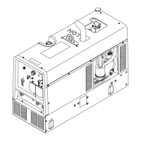
Provides instructions for safely installing the welding generator, including placement and grounding.
Details the correct procedure for installing the exhaust pipe for proper ventilation.
Outlines essential pre-start checks for engine fluids, fuel, and battery status before operation.
Step-by-step guide for adding coolant to the radiator, including air purging.
Details the correct procedure for connecting the battery terminals to the generator.
Explains how to connect work and electrode cables to the correct output terminals for welding.
Provides guidance on selecting the correct weld cable size based on length and amperage for optimal performance.
Explains the function and pinout of the remote 14 receptacle for connecting external controls.
Details how to adjust the MIG weld puddle consistency for better weld quality.
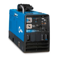
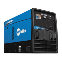
Identifies and explains the function of each control on the front panel of the welding generator.
Describes how to connect and use remote controls for amperage and voltage adjustment.
Details the auxiliary power receptacles, their ratings, and associated circuit breakers.
Explains the features and operation of optional GFCI and Australian style auxiliary power receptacles.
Provides wiring instructions for an optional 240 volt plug for auxiliary power connections.
Displays the maintenance label detailing service intervals and specifications for the diesel engine.
Outlines routine maintenance tasks and their recommended intervals based on operating hours.
Provides steps for servicing the air cleaner element, including cleaning or replacement procedures.
Details procedures for servicing the engine's cooling system, including coolant and hoses.
Explains how to inspect and maintain the optional spark arrestor screen.
Covers maintenance procedures for the engine's fuel and lubrication systems, including oil and filters.
Guides on adjusting engine speed by verifying and adjusting fuel and throttle solenoids.
Details the overload protection mechanisms, including circuit breakers and fuses, and their locations.
Provides solutions for common welding, auxiliary power, and engine operational issues.
Explains what wetstacking is and provides methods to prevent it during engine run-in.
Details the step-by-step procedure for running in the generator using a load bank.
Outlines the process for running in the generator using a resistance grid.
Provides guidance on selecting appropriate equipment for use with auxiliary power outlets.
Details the procedure for properly grounding the generator to a truck or trailer frame for safety.
Explains how to ground the generator when supplying power to building systems according to codes.
Guides on calculating power requirements for various types of equipment, including starting and running watts.
Lists approximate starting and running watts for various industrial motors by horsepower.
Provides approximate power requirements for common farm and home equipment.
Lists approximate power requirements for various contractor tools and equipment.
Details how to calculate the power required for starting electric motors, including starting amperage.
Offers guidelines on managing load and understanding generator supply limits to prevent damage.
Illustrates typical wiring connections for supplying standby power from the generator during outages.
Provides charts to help select the correct extension cord size based on current, load, and length.
| Max Output | 300 A |
|---|---|
| Fuel Type | Gasoline |
| Frequency | 60 Hz |
| Power Factor | 1.0 |
| Type | Engine Driven Welding Generator |
| Welding Amperage Range | 30-300A |
| Output Range | 20 - 300 Amps |
| Open Circuit Voltage | 70V DC |
| Engine Power | 14 HP |
| Fuel Tank Capacity | 12 Gallons |
| Dimensions | 30 x 21 x 23 inches |