OM-169 510 Page 25
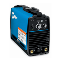
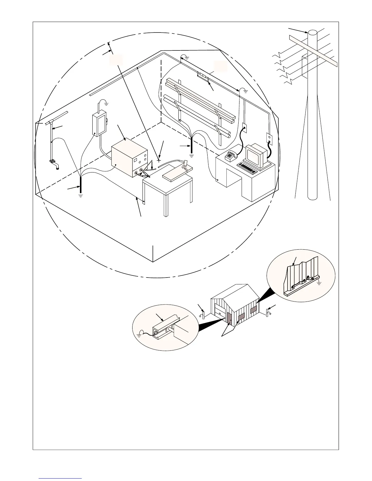
1 Plasma Arc Welding Power Source
Ground metal machine case, line discon-
nect device, input supply, and workpiece (if
required).
2 Center Point Of Welding Zone
Midpoint between high-frequency source
and welding torch.
3 Welding Zone
A circle 50 ft (15 m) from center point in all
directions.
4 Torch And Work Cables
Keep cables close together.
5 Conduit Joint Bonding And Grounding
Electrically join (bond) all conduit sections
using copper straps or braided wire. Ground
conduit every 50 ft (15 m).
6 Water Pipe And Fixtures
Ground water pipe every 50 ft (15 m).
7 External Power Or Telephone Lines
Locate high-frequency source at least 50 ft
(15 m) away from power and phone lines.
8 Metal Building Panel Bonding
Methods
Bolt or weld building panels together, install
copper straps or braided wire across
seams, and ground frame.
9 Grounding Rod
Consult the National Electrical Code for
specifications.
10 Windows And Doorways
Cover all windows and doorways with
grounded copper screen of not more than
1/4 in (6.4 mm) mesh.
11 Overhead Door Track
Ground the track.
8
9
11
10
S-0755
1
2
3
50 ft
(15 m)
Welding Zone
4
7
50 ft
(15 m)
Metal Building
Nonmetal Building
9
9
5
9
6
Ground All
Metal Objects
And All Wiring
In Welding Zone
Using #12 AWG Wire
Ground
Workpiece
If Required
By Codes
Figure 6-3. Correct Installation