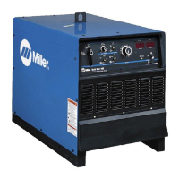
What to do if Miller Gold Star has no weld output but the power switch light and fan are on?
R
Robert TorresJul 26, 2025
If your Miller Welding System shows no weld output, but the power switch light is on and the fan is running, here's what you can do:
1. If you're using a remote control, make sure the Output (Contactor) switch is in the Remote position and the remote control is properly connected. If you're not using a remote, ensure the switch is in the On position.
2. If the unit overheated, let it cool down with the fan on.
If these steps don't resolve the issue, the remote control may need to be checked, repaired, or replaced. Also, a Factory Authorized Service Agent can check the control board PC1.
D
daviddavenportAug 11, 2025
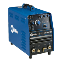
What to do if Miller Gold Star Welding System has no weld output and is completely inoperative?
T
tinacolemanAug 11, 2025
If your Miller Welding System has no weld output and is completely inoperative, consider the following:
* Ensure the line disconnect switch is in the On position.
* Check fuse F1 and replace it if necessary.
* Check and replace any blown line fuses, or reset the circuit breaker.
* Verify proper input power connections.
* Confirm the correct jumper link position.