A complete Parts List is available at www.MillerWelds.com
OM-246193 Page 24
SECTION 6 − GENERAL OPERATION
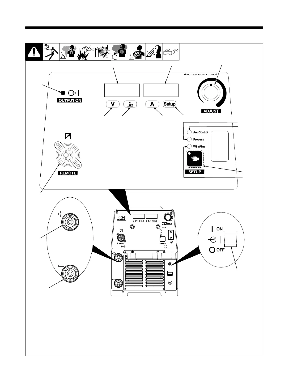
6-1. Front Panel
Weld process operation sections de-
scribe functionality of the identified items.
1 Remote 14 Receptacle
2 Output ON Indicator Light
3 Volts Indicator
4 Left Display
5 Arc Length Indicator
6 Right Display
The meters display the actual weld output
values after arc initiation and remains dis-
played for approximately three seconds
after the arc is broken.
7 Amps Indicator
8 Setup Indicator
9 Adjust Control
10 Process Indicator
11 Arc Control Indicator
12 Setup Button
13 Wire/Gas Type Indicator
14 Power Switch
15 Weld Output Terminal (−)
16 Weld Output Terminal (+)
Ref. 804772-B / 235550-A
14
4
6
9
1
12
2
16
15
3
5
7
8
13
11
10

 Loading...