EasyManua.ls Logo

Miller Auto-Axcess 300 CE - User Manual

Miller Auto-Axcess 300 CE
76 pages
Print Icon
To Next Page IconTo Next Page
Loading...
OM-231185Y 201604
Auto-Axcess 300
CE
Processes
Description
MIG (GMAW) Welding
Pulsed MIG (GMAW-P)
Flux Cored (FCAW) Welding
Automatic Welding
Automatic Welding Interface And
Arc Welding Power Source
File: Advanced Manufacturing Systems
Visit our website at
www.MillerWelds.com/ams

Table of Contents

Questions and Answers

  • B
    Blake BrownSep 8, 2025
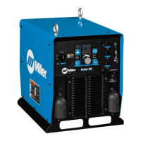
    What does Stop Error mean on Miller Auto-Axcess 300 CE Welding System?
    • R
      rebeccaskinnerSep 9, 2025
      Stop Error on Miller Welding System indicates obstructions in the wire feed system or a faulty wire drive system. Check wire feed and wire drive systems. Press Jog/Purge button to clear error.
  • A
    alec94Aug 23, 2025
    How to fix a Gas Flow Error on Miller Auto-Axcess 300 CE Welding System?
    • C
      Chad FloydAug 23, 2025
      To fix a Gas Flow Error on your Miller Welding System, which indicates no gas flow to the gun, reset the system by re-establishing gas flow to the gun and then pressing the Jog/Purge button.
  • C
    Carol WalshAug 25, 2025
    What should I do if my Miller Auto-Axcess 300 CE shows a Flow Error?
    • D
      Daniel MurrayAug 25, 2025
      If your Miller Welding System shows a Flow Error, it means there is no gas flow to the gun. You can reset it by re-establishing gas flow to the gun, and then pressing the Jog/ Purge button.
  • T
    tiffany87Aug 27, 2025
    Why am I getting a Motor Over Current Error on my Miller Welding System, and how do I fix it?
    • H
      Herbert JohnsonAug 27, 2025
      A Motor Over Current Error on your Miller Welding System indicates that the motor has been drawing too much current for too long. To fix it, reduce the wire feed speed or the wire feeder torque load/duty cycle. Then, press the Jog/Purge button to clear the error.
  • A
    Alexander FergusonAug 27, 2025
    How do I clear an Emergency Stop Error on a Miller Welding System?
    • D
      Donna ElliottAug 28, 2025
      To clear an Emergency Stop Error on your Miller Welding System, press the Jog/Purge button.
  • V
    vtorresSep 22, 2025
    What does Please Wait Error mean on Miller Auto-Axcess 300 CE Welding System?
    • A
      alexander71Sep 22, 2025
      A Please Wait Error on your Miller Welding System indicates the user interface board lost data communications. Press the Jog/Purge button to clear the error.
  • J
    John BarnesSep 16, 2025
    How to fix Robot Memory Error on Miller Auto-Axcess 300 CE?
    • J
      Jill BryantSep 16, 2025
      To fix a Robot Memory Error on your Miller Welding System, which indicates robot lost memory data, press the Jog/Purge button.
  • K
    Kristin SparksSep 18, 2025
    What does Weld Wait Error mean on Miller Welding System?
    • A
      Amber VaughanSep 18, 2025
      A Weld Wait Error on your Miller Welding System indicates the unit was not ready for a weld sequence. Press the Jog/Purge button to clear the error.
  • J
    joseph74Sep 7, 2025
    What does Arc Start Error mean on Miller Auto-Axcess 300 CE Welding System?
    • A
      andrew29Sep 7, 2025
      An Arc Start Error on your Miller Welding System indicates the contactor either is or was active, but the system failed to start an arc. Conditions for a valid arc start are at least 50% of arc start current, voltage less than 60 volts, and voltage greater than min. valid arc voltage (default is 22.5 volts).
  • D
    Douglas WintersSep 4, 2025
    What should I check if my Miller Welding System shows a Thermal Over Temperature Error?
    • T
      Theresa SmithSep 4, 2025
      If your Miller Welding System shows a Thermal Over Temperature Error, it indicates that one or more of the inverter engines overheated. Check the fan on the inverter engine(s) and weld currents.

Summary

General Safety Precautions

Safety Symbol Definitions

Explains the meaning of warning symbols used in the manual.

Arc Welding Hazard Overview

Details general hazards associated with arc welding processes.

Specific Safety Warnings

Welding Fume and Gas Hazards

Describes hazards related to welding fumes and gases and ventilation requirements.

Arc Ray and Spark Hazards

Explains the dangers of arc rays, sparks, and necessary protective measures.

Fire, Explosion, and Gas Hazards

Covers fire, explosion, gas buildup risks associated with welding operations.

Regulatory and EMF Safety Information

Principal Safety Standards

Lists key safety standards and their sources for welding and cutting.

Product Specifications

Operational Specifications

Duty Cycle and Overheating Precautions

Explains duty cycle and precautions against overheating.

Installation and Connection

System Connection Diagram

Illustrates the connections between the power source, robot, and other components.

Weld Terminal Connections

Connecting to Weld Terminals

Explains how to properly connect weld cables to the output terminals.

Output Terminal and Cable Selection

Weld Output Terminals and Cable Sizing

Guides on selecting appropriate weld cable sizes based on length and current.

Electrical Service Requirements

Electrical Service Requirements

Provides recommendations for electrical service installation and connections.

Power Connection

Connecting 3-Phase Input Power

Explains the procedure for connecting 3-phase input power to the unit.

Operation and Control

Front Panel Interface

Front Panel Control Layout

Describes the functions of the controls on the front panel of the unit.

Front Panel Controls and Switches

Front Panel Controls and Switches

Continues the description of front panel controls, indicators, and switches.

Robot Integration and Calibration

Robot Calibration Procedure

Details the procedure for calibrating the power source to the robot.

Robot Auto-Calibration

Robot Auto-Calibration Sample Programs

Provides sample programs for robot auto-calibration on different platforms.

Unit Reset Function

Reset Mode and Factory Defaults

Explains how to reset the unit to factory default programs.

Maintenance

Routine Maintenance Schedule

Outlines periodic maintenance tasks for the unit.

Servicing Safety Precautions

Servicing Symbol Definitions

Explains warning symbols used specifically for servicing procedures.

General Servicing Hazards

Details hazards that apply when servicing the equipment.

Troubleshooting and Error Codes

Error Code Reference

Error Code Reference Table

Lists error codes displayed on the interface and their corresponding sections for troubleshooting.

Specific Error Code Explanations

Internal Component Checks

Module Diagnostic LEDs

General Troubleshooting Guide

General Troubleshooting Guide

Provides a table of common troubles and their remedies.

Electrical Diagrams

Warranty and Service Information

Miller Auto-Axcess 300 CE Specifications

General IconGeneral
BrandMiller
ModelAuto-Axcess 300 CE
CategoryWelding System
LanguageEnglish

Related product manuals