Do you have a question about the Miller PRO 300 and is the answer not in the manual?
Explains safety symbols, arc welding, engine, and moving parts hazards.
Details burns from steam/coolant/battery acid, engine heat/exhaust, compressed air, and hot metal risks.
Safety for unit installation, operation, and maintenance, including static and trailer tilting.
California Proposition 65 warnings, safety standards, and EMF information.
Explanations of various warning labels found on the equipment.
Definitions and meanings of symbols used in the manual.
Detailed specifications for welding output, power, and engine.
Physical dimensions, weight, and safe operating angles.
Graphs showing voltage and amperage output capabilities.
Information on duty cycle limits and overheating prevention.
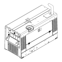
Procedures for safely installing the welding generator.
Instructions for securely mounting the welding generator.
Procedure for activating the dry charge battery.
Instructions for correctly connecting the battery.
Essential checks before starting the engine.
Guide for choosing appropriate weld cable sizes.
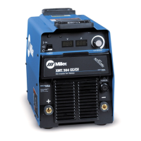
Overview of the controls located on the front panel of the unit.
Detailed explanation of each front panel control's function.
How to use the Process/Contactor switch for different welding modes.
How to use remote controls for voltage and amperage adjustment.
Information on operating and using the auxiliary power receptacles.
Schedule and tasks for regular maintenance of the unit.
Procedures for cleaning and servicing the air cleaner.
Instructions for servicing the engine's cooling system.
Maintenance procedures for fuel and lubrication systems.
Explanation of overload protection devices like circuit breakers and fuses.
General troubleshooting guide for welding and generator power issues.
Troubleshooting specific engine-related problems.
Detailed electrical schematic of the welding generator.
Explanation of wetstacking and its causes during engine run-in.
Step-by-step procedure for run-in using a load bank.
Step-by-step procedure for run-in using a resistance grid.
Instructions for grounding the generator frame to vehicle frames.
Calculating power requirements for connected equipment.
Calculating starting power requirements for motors.
Guidelines on managing generator load and supply capacity.
Exploded view and parts list for the main assembly.
| Open-Circuit Voltage (OCV) | 80 VDC |
|---|---|
| Weight | 375 lb (170 kg) |
| Output Current Range | 5 - 400 A |
| Rated Output | 300 A at 32 VDC, 60% Duty Cycle |
| Welding Amperage Range | 5 - 400 A |
| Dimensions | H: 36 in (914 mm) W: 25 in (635 mm) L: 40 in (1016 mm) |
| Processes | MIG (GMAW), Stick (SMAW), TIG (GTAW), Flux-Cored (FCAW) |