OM-4422 Page 26
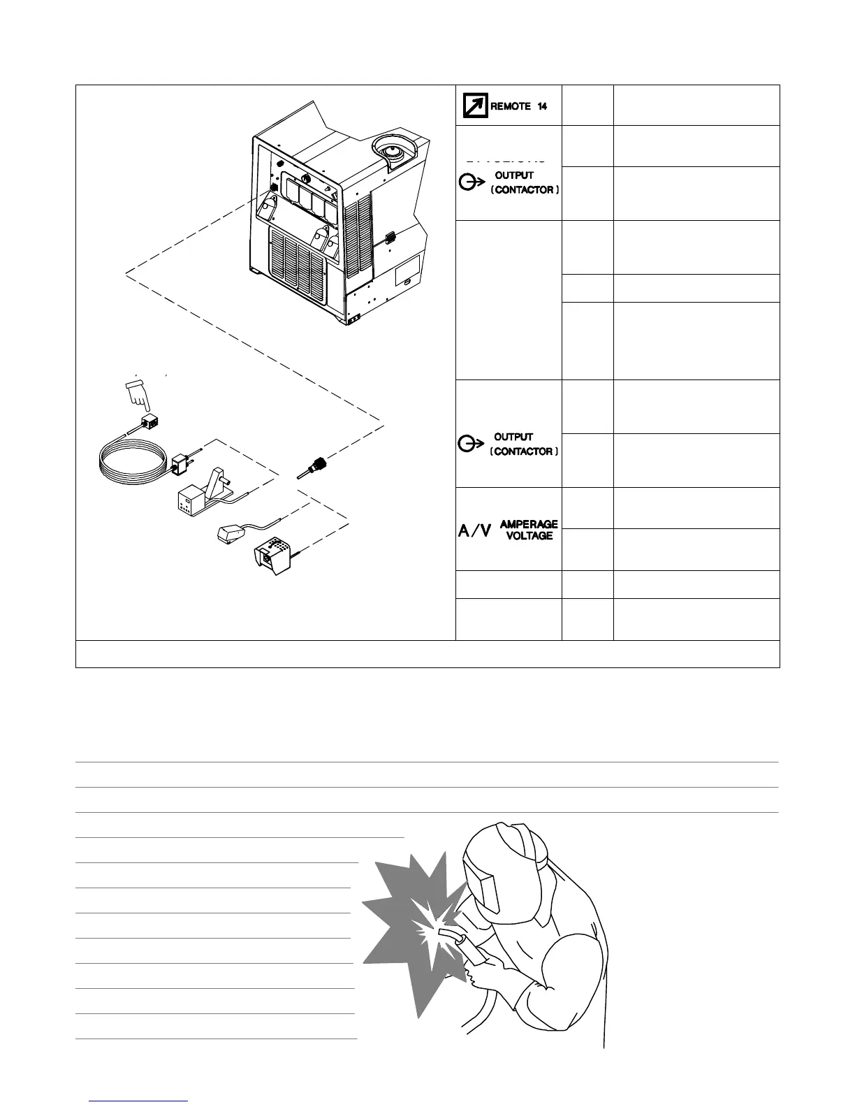
5-9. Connecting To Remote 14 Receptacle RC14
Socket* Socket Information
24 VOLTS AC
A 24 volts ac. Protected by circuit
breaker CB8.
B Contact closure to A completes
24 volt ac contactor control
circuit.
C Output to remote control:+10
volts dc in MIG mode; 0 to +10
volts dc in Stick or TIG mode.
REMOTE
D Remote control circuit common.
LDR-14 long
distance remote
(includes 120 V
receptacle)
CONTROL
E DC input command signal: 0 to
+10 volts from min. to max. of
remote control with Voltage/
Amperage Adjust control at
max.
115 VOLTS AC
I
115 volts, 10 amperes, 60 Hz
ac. Protected by circuit breaker
CB7.
J
Contact closure to I completes
115 volt ac contactor control
circuit.
F
Current feedback: 1 volt per
100 amperes.
H Voltage feedback: 1 volt per 10
arc volts.
803 562
GND
K Chassis common.
NEUTRAL G Circuit common for 24 and 115
volt ac circuit.
*The remaining sockets are not used.
Notes
Work like a Pro!
Pros weld and cut
safely. Read the
safety rules at
the beginning
of this manual.
 Loading...