
K
Kimberly VillaAug 14, 2025
What to do if there's no 115 volts AC output at the receptacle on my Miller Welding System?
- SSteven WilsonAug 15, 2025
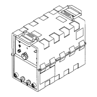
If there is no 115 volts AC output at the Remote 14 receptacle RC1 or the optional duplex receptacle on your Miller Welding System, reset circuit breaker CB1 if necessary. Check the wiring and connections of the receptacle(s).