T
Tommy AdamsAug 1, 2025
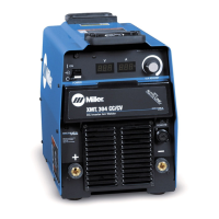
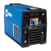
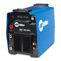
How to fix a Miller Welding System with no weld output and completely inoperative?
- AAndrea PierceAug 2, 2025
If your Miller Welding System isn't producing any weld output and is completely inoperative, first ensure the line disconnect switch is in the On position. Then, check and replace the line fuses if necessary, or reset the circuit breaker. Finally, verify that the input power connections are properly connected.