Do you have a question about the Miller XMT 450 CC and is the answer not in the manual?
Explains danger, warning, and notice symbols used in the manual.
Details hazards like electric shock, moving parts, hot parts, and falling equipment.
States product contains chemicals known to cause cancer and reproductive harm.
Discusses EMF effects, protective measures, and user responsibility for interference.
Explains symbols for WEEE, gloves, insulation, power disconnect, fumes, flammables, sparks.
Defines symbols for amperage, voltage, current, frequency, etc.
Describes features like LVCT, Wind Tunnel Technology, Fan-On-Demand, Auto Remote Sense, Lift-Arc, Adaptive Hot Start.
Explains DIG and Inductance controls for arc characteristics.
States the location of serial number and rating label for product identification.
Provides a table of input power, output, amperage, voltage, KVA, and KW ratings.
Lists hole layout dimensions, overall dimensions, and weight of the unit.
Details IP rating, EMF information, and EMC compliance.
Explains duty cycle, effects of overheating, and related warnings.
Shows minimum and maximum voltage/amperage output capabilities for CC and CV modes.
Provides guidelines for choosing an installation location, including movement and tipping precautions.
Details how to select appropriate weld cable sizes based on amperage and cable length.
Illustrates correct and incorrect installation of weld output cables.
Explains the function of each pin in the 14-pin remote receptacle.
Identifies the 115V AC receptacle and its associated protective circuit breakers.
Details how to connect shielding gas and explains gas solenoid operation for TIG processes.
Provides recommendations for input voltage, amperage, fuses, and conductor sizing.
Illustrates the wiring diagram and steps for connecting the main input power.
Identifies and describes the function of each control and display on the front panel.
Details the switch positions, corresponding processes, and output/panel adjustments.
Shows the typical setup for Gas Tungsten Arc Welding (GTAW).
Explains how to set up and operate the Scratch Start TIG welding mode.
Details the setup and operation of the Lift-Arc TIG welding mode.
Explains operating Scratch Start TIG with a remote control.
Shows the setup for Gas Metal Arc Welding/Flux Cored Arc Welding with a remote feeder.
Explains how to set up and operate the MIG welding mode, including Arc Control.
Shows the setup for Pulsed Gas Metal Arc Welding with a remote feeder and pulsing device.
Explains operating the Pulsed MIG welding mode, noting the requirement for an external pulsing device.
Shows the connection diagram for a Voltage-Sensing Feeder setup.
Explains how to set up and operate the V-Sense Feeder welding mode.
Shows the typical setup for Shielded Metal Arc Welding and Air Carbon Arc cutting.
Explains operating Stick welding with a remote control, including Adaptive Hot Start and Arc Control.
Details setting up and operating Stick welding, including Adaptive Hot Start and Arc Control (Dig).
Describes the optional low OCV configuration for Stick and Scratch Start TIG modes.
Explains three ways to configure remote control operation and meter display.
Presents a block diagram illustrating the major components and signal flow.
Outlines essential checks to perform before applying power to avoid further damage.
Details how to safely remove the case and measure input capacitor voltage.
Describes visual inspection and diode testing procedures for the input rectifier module.
Explains how to test IGBT modules using a tester or DMM.
Details testing procedures for diodes, resistors, and capacitors on the interconnect board.
Describes visual inspection and diode testing for output diodes.
Explains how to verify the contacts and coil resistance of the input contactor.
Describes how to check tank capacitors for shorts and capacitance.
Lists common troubles and their remedies, guiding users through diagnostics.
Explains the meaning of help codes displayed by the unit and their potential causes/solutions.
Provides the main circuit diagram for troubleshooting purposes.
Lists expected resistance and voltage readings for various points in the circuit diagram.
Details testing procedures and test points for the Inverter Control Board PC1.
Lists specific voltage readings for various pins on the Inverter Control Board PC1.
Explains the function of diagnostic LEDs on the Inverter Control Board PC1.
Provides information for testing the Interconnect Board PC2.
Lists specific voltage readings for various pins on the Interconnect Board PC2.
Details testing procedures for the Front Panel/Display Board PC3.
Lists specific voltage readings for various pins on the Front Panel/Display Board PC3.
Describes how to check the unit's output after servicing is completed.
Details the procedure to enable optional low OCV welding modes.
Explains how to check for bus voltage imbalance, especially after component replacement.
Outlines maintenance tasks to be performed at 3-month and 6-month intervals.
Describes how to safely blow out dust and debris from the unit's interior.
Provides the detailed circuit diagram for 400 Volt models.
Shows the wiring diagram for 400 Volt models, part one.
Shows the wiring diagram for 400 Volt models, part two.
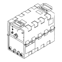
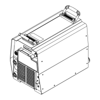
Illustrates the assembly of various parts of the welding unit.
Provides a detailed list of part numbers, descriptions, and quantities.
| Brand | Miller |
|---|---|
| Model | XMT 450 CC |
| Category | Welding System |
| Language | English |