EasyManua.ls Logo

Miller ALT 304 - User Manual

Miller ALT 304
32 pages
Print Icon
To Next Page IconTo Next Page
Loading...
Visit our website at
www.MillerWelds.com
Processes
Description
Multiprocess Welding
Arc Welding Power Source
OM-2231 198 248J
August 2003
ALT 304

Questions and Answers

  • A
    awagnerAug 1, 2025
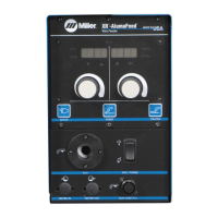
    What to do if there is no 115 volts ac output at the duplex receptacle of my Miller ALT 304 Welding System?
    • J
      Jonathan WilsonAug 1, 2025
      If there is no 115 volts AC output at the duplex receptacle of your Miller Welding System, try resetting circuit breaker CB1.
  • J
    Jessica DicksonAug 7, 2025
    How to fix no 24 volts ac output at the Remote 14 receptacle on my Miller ALT 304?
    • R
      Rodney PrattAug 7, 2025
      If there is no 24 volts AC output at the Remote 14 receptacle on your Miller Welding System, try resetting circuit breaker CB2.
  • K
    Karen Griffin PhDAug 14, 2025
    What to do if my Miller ALT 304 has no weld output but the meter display is on?
    • G
      Gary ManningAug 14, 2025
      If your Miller Welding System shows the meter display is on but there's no weld output, several factors could be at play. If you are using a remote control, ensure the mode switch is set to enable output control at the Remote 14 receptacle. Also, the input voltage may be outside the acceptable range of variation, so consider checking or repairing the remote control. Finally, the unit might have overheated; in this case, allow it to cool down with the fan on.
  • K
    Kristi TurnerAug 19, 2025
    How to fix a Miller Welding System with erratic or improper weld output?
    • C
      Cindy WilliamsAug 19, 2025
      To resolve erratic or improper weld output in your Miller Welding System, start by ensuring you are using the correct size and type of weld cable. Additionally, inspect all weld connections to make sure they are clean and tight.
  • P
    Paul AlexanderAug 25, 2025
    What to do if my Miller ALT 304 has no weld output and is completely inoperative?
    • C
      cmayAug 26, 2025
      If your Miller Welding System is completely inoperative with no weld output, first ensure that the line disconnect switch is in the On position. Next, check the line fuses and replace them if necessary, or reset the circuit breaker. Finally, verify that the input power connections are properly connected.

Summary

Safety Precautions

Symbol Usage

Explains symbols indicating possible hazards in procedures.

Arc Welding Hazards

Details potential dangers during arc welding, including electric shock, fumes, and heat.

Additional Symbols For Installation, Operation, And Maintenance

Lists symbols for fire, falling units, static, and moving parts hazards.

Principal Safety Standards

Lists key safety standards and codes for welding and cutting processes.

EMF Information

Discusses electromagnetic fields and recommendations for minimizing exposure.

Introduction

Specifications

Provides technical specifications including input power, output range, and voltage/amperage ratings.

Volt-Ampere Curves

Illustrates minimum and maximum voltage/amperage output capabilities for different modes.

Duty Cycle And Overheating

Explains duty cycle percentages and consequences of overheating the welding unit.

Installation

Selecting a Location

Guides on choosing a suitable location for the welding unit, considering dimensions and movement.

Weld Output Receptacles And Selecting Cable Sizes

Details weld output receptacles and provides charts for selecting appropriate cable sizes based on length.

Remote 14 Receptacle Information

Describes the function of each socket in the Remote 14 receptacle for control and feedback.

Optional Gas Valve Operation And Shielding Gas Connection

Explains how to connect and operate the optional gas valve and shielding gas supply.

Optional 115 Volts AC Duplex Receptacle And Circuit Breakers

Details the 115V AC receptacle, its sharing with the Remote 14, and protective circuit breakers.

Electrical Service Guide

Provides input voltage and amperage requirements for single-phase and three-phase power.

Connecting Input Power

Illustrates how to connect the input power supply, emphasizing grounding conductor connection first.

Operation

Front Panel Controls

Identifies and explains the function of each control on the front panel of the welding unit.

Mode Switch Settings

Outlines the different mode switch settings and their corresponding processes and output controls.

Lift-Arc TIG Procedure

Details the step-by-step procedure for initiating an arc using the Lift-Arc TIG method.

Maintenance & Troubleshooting

Routine Maintenance

Describes regular maintenance tasks to be performed at specific intervals for optimal performance.

Blowing Out Inside Of Unit

Provides instructions on how to clean the internal components of the unit by blowing out dust.

Voltmeter;Ammeter Help Displays

Explains the meaning of various help displays shown on the voltmeter/ammeter for troubleshooting.

Troubleshooting

Lists common problems, their causes, and suggested remedies for troubleshooting the welding unit.

Electrical Diagram

Parts List

Warranty

Miller ALT 304 Specifications

General IconGeneral
BrandMiller
ModelALT 304
CategoryWelding System
LanguageEnglish

Related product manuals