EasyManua.ls Logo

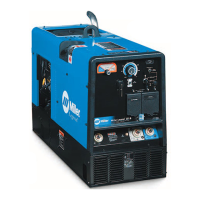
Miller Legend 301 G User Manual

Miller Legend 301 G
86 pages
To Next Page IconTo Next Page
Page #1 background imageLoading...
Page #1 background image
Processes
TM-4411A March 2003
Eff. w/Serial Number LC357086
Visit our website at
www.MillerWelds.com
Description
TIG (GTAW) Welding
Stick (SMAW) Welding
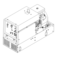
Engine Driven Welding Generator
MIG (GMAW) Welding &
Flux Cored (FCAW) Welding-
With Voltage Sensing Feeder
Miller Legend 301 G
R

Table of Contents

Question and Answer IconNeed help?

Do you have a question about the Miller Legend 301 G and is the answer not in the manual?

Miller Legend 301 G Specifications

General IconGeneral
BrandMiller
ModelLegend 301 G
CategoryWelding System
LanguageEnglish

Summary

Safety Precautions for Servicing

Symbol Usage

Explains safety symbols used in the manual.

Servicing Hazards

Details potential hazards during maintenance and servicing.

EMF Information

Discusses electromagnetic field effects and precautions.

Definitions

Symbol Definitions

Defines various symbols used in the manual for clarity.

Specifications

Description

Overview of the multiprocess engine-driven welder and AC generator.

Weld, Power, And Engine Specifications

Details welding modes, power ratings, and engine specs.

Dimensions, Weights, and Operating Angles

Provides physical dimensions, weight, and operating angle limits.

Fuel Consumption

Graph showing fuel consumption at different loads and speeds.

Generator Power Curve

Graph illustrating AC generator power output vs. amperage.

Duty Cycle

Explains duty cycle and shows performance at different amperage levels.

Stick And MIG Mode Volt-Ampere Curves

Displays voltage-amperage characteristics for Stick and MIG modes.

DC TIG Mode Volt-Ampere Curves

Shows voltage-amperage characteristics for DC TIG mode.

Installation

Installing Welding Generator

Instructions for safely moving, locating, mounting, and grounding the unit.

Engine Prestart Checks

Steps for checking fluids, fuel, and oil before starting the engine.

Activating The Dry Charge Battery

Procedure for preparing and installing a dry charge battery.

Connecting The Battery

Steps for correctly connecting the unit's battery.

Installing Exhaust Pipe

Guidance on properly installing the exhaust pipe.

Connecting To Weld Output Terminals

How to connect welding cables to the output terminals.

Selecting Weld Cable Sizes

Chart to help choose appropriate weld cable sizes based on length and current.

Remote Receptacle Information

Details on the remote receptacle functions and pinouts.

Adjusting Wire (MIG) Weld Puddle Consistency

Instructions for changing wire feed settings to alter weld puddle characteristics.

Operating Welding Generator

Front Panel Controls

Identifies and illustrates the controls on the front panel.

Description Of Front Panel Controls

Detailed explanation of each front panel control's function.

Process Switch

How to use the process switch to select welding modes.

Remote Amperage/Voltage Control

Guide to using remote controls for amperage and voltage adjustment.

Operating Auxiliary Equipment

60 Hz Generator Power Receptacles And Circuit Breakers

Information on 120/240V receptacles and their circuit breakers.

Variable Frequency (Hz) Generator Power Receptacle RC3

Details on the variable frequency AC receptacle.

Wiring Optional 240 Volt Plug

Instructions for wiring a 240V plug for various load configurations.

Maintenance

Routine Maintenance

Schedule and tasks for regular preventive maintenance.

Maintenance Label

Information found on the unit's maintenance label.

Servicing Optional Spark Arrestor

Steps for cleaning and inspecting the spark arrestor screen.

Servicing Air Cleaner

Procedure for cleaning or replacing the air cleaner element and wrapper.

Changing Engine Oil, Oil Filter, And Fuel Filter

Guide for performing oil and fuel filter changes.

Overload Protection

Explanation of circuit breakers and fuses for overload protection.

Theory Of Operation

Explanation Of Electrical Parts

Safety Precautions – Read Before Using This Guide

Safety warnings specific to electrical parts.

Explanation Of Electrical Parts

Defines common electrical components used in the unit.

Troubleshooting

Troubleshooting Tables

Tables listing common problems and their remedies.

Troubleshooting Circuit Diagram For Welding Generator (AC/DC Models)

Circuit diagram for troubleshooting the welding generator.

Troubleshooting Values For Circuit Diagram (AC/DC Models)

Test values for the welding generator circuit diagram.

Waveforms For Section 10-2

Oscilloscope waveforms for troubleshooting analysis.

Power Board PC1 Testing Information

Information on testing Power Board PC1.

Power Board PC1 Test Point Values

Specific voltage readings for Power Board PC1 test points.

Control Board PC2 Testing Information

Information on testing Control Board PC2.

Control Board PC2 Test Point Values

Specific voltage readings for Control Board PC2 test points.

Power Board PC7 Testing Information

Information on testing Power Board PC7.

Power Board PC7 Test Point Values

Specific voltage readings for Power Board PC7 test points.

Replacing Brushes And Cleaning Slip Rings

Procedure for replacing brushes and cleaning slip rings.

Adjusting Electronic Governor

Steps for adjusting the electronic governor for proper engine speed.

Checking Unit Output After Servicing

Procedure to verify unit output after maintenance.

Disassembly and Reassembly

Disassembly Of Unit

Steps for disassembling the entire welding generator unit.

Disassembly Of Generator

Specific instructions for disassembling the generator component.

Electrical Diagrams

Circuit Diagram - Welding Generator (AC/DC Models)

Overall circuit diagram for the welding generator.

Circuit Diagram - Weld Power Board PC1

Detailed circuit diagram for the weld power board.

Circuit Diagram - Control Board PC2

Detailed circuit diagram for the control board.

Circuit Diagram - Generator Power Board PC7

Detailed circuit diagram for the generator power board.

Circuit Diagram - HF Filter Board PC3

Detailed circuit diagram for HF Filter Board PC3.

Circuit Diagram - HF Filter Board PC5

Detailed circuit diagram for HF Filter Board PC5.

Parts List

Figure 13-1. Main Assembly

Exploded view and parts list for the main assembly.

Figure 13-2. Panel, Front w/Components

Exploded view and parts list for the front panel.

Figure 13-3. Bracket w/Components

Exploded view and parts list for bracket assemblies.

Figure 13-4. Generator

Exploded view and parts list for the generator component.

Related product manuals