EasyManua.ls Logo

Miller Multimatic 220 AC/DC User Manual

Miller Multimatic 220 AC/DC
80 pages
To Next Page IconTo Next Page
Page #1 background imageLoading...
Page #1 background image
OM-281426C 202007
Multimatic 220
AC/DC
ProcessesProcesses
Description
Multiprocess Welding
Arc Welding Power Source
Wire Feeder
File: Multiprocess
®
For product information,
Owner’s Manual translations,
and more, visit
www.MillerWelds.com

Table of Contents

Other manuals for Miller Multimatic 220 AC/DC

Questions and Answers:

Miller Multimatic 220 AC/DC Specifications

General IconGeneral
Input Voltage120/240 V
Weight56 lb (25.4 kg)
Input Phase1-Phase
Input Hz50/60 Hz
TIG Lift ArcYes
TIG HF StartYes
Wire Size Range0.024 - 0.035 in (0.6 - 0.9 mm)
ProcessesMIG, Stick, TIG
Output Voltage Range10 - 24.5 V

Summary

Owner's Manual

SECTION 1 – SAFETY PRECAUTIONS - READ BEFORE USING

1-1. Symbol Usage

Explains the meaning of warning symbols used throughout the manual.

1-2. Arc Welding Hazards

Details hazards like electric shock, moving parts, and hot parts during arc welding.

1-3. Additional Hazards For Installation, Operation, And Maintenance

Fire, Explosion, and Overuse Hazards

Warns about fire, explosion, and overheating risks during installation and operation.

Physical Injury Hazards

Details risks from falling equipment, sparks, moving parts, wire, and batteries.

Electrical Component Hazards

Warns about electrostatic discharge damaging electronic components.

General Operational Instructions

Emphasizes reading all labels and the owner's manual before operation.

1-4. California Proposition 65 Warnings

1-5. Principal Safety Standards

1-6. EMF Information

About Implanted Medical Devices:

Advises medical implant wearers to consult doctors before operating near welding equipment.

SECTION 3 – DEFINITIONS

3-1. Additional Safety Symbols And Definitions

Explains additional safety symbols and their meanings.

3-2. Miscellaneous Symbols And Definitions

Provides definitions for various symbols related to welding parameters and functions.

SECTION 4 – SPECIFICATIONS

Unit Identification and Licensing

Covers serial number location and software licensing agreement.

Weld Parameter Information

Notes on default parameters and specifications for MIG, TIG, and Stick welding.

4-7. Environmental Specifications

A. IP Rating

Details the Ingress Protection (IP) rating and suitability for indoor use.

B. Temperature Specifications

Outlines operating and storage temperature ranges for the equipment.

4-8. Dimensions And Weight

4-9. Duty Cycle And Overheating For MIG (GMAW)

4-10. Duty Cycle And Overheating For TIG (GTAW)

4-11. Duty Cycle And Overheating For Stick (SMAW)

SECTION 5 – INSTALLATION

5-1. Selecting A Location

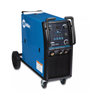
Provides guidelines for selecting a suitable and safe location for the unit.

5-2. Multi-Voltage Plug (MVP) Connection

5-3. Electrical Service Guide

5-4. Input Power Extension Cord Data

5-5. Connecting 120 Volt Input Power

5-6. Connecting 1-Phase Input Power For 240 VAC

5-7. Generator / Inverter Requirements

5-8. Stick Welding Connections

5-9. TIG Welding Connections

5-10. MIG Welding Connections

5-11. MIG Gun Connection Inside Unit

5-12. Connecting Shielding Gas Supply

5-13. Installing Wire Spool And Adjusting Hub Tension

5-14. Threading Welding Wire

5-15. Removing MIG Gun To Replace With A Spool Gun

SECTION 6 – OPERATION

6-1. Controls

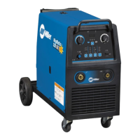
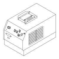
Identifies and explains the function of the main controls on the unit.

6-2. Controls, TIG Aluminum Manual Mode

6-3. Controls, TIG Steel/Stainless Manual Mode

6-4. Controls, Stick Manual Mode

6-5. Controls, MIG Manual Mode

6-6. Welding Parameter Chart – 120V

6-7. Welding Parameter Chart – 240V

6-8. Entering Setup Menu

6-9. Internal Motor 24 Inch Calibration (Menu 1 Of 12)

6-10. Internal Motor Run-In Speed (Menu 2 Of 12)

6-11. Spoolmate ™™™ 24 Inch Calibration (Menu 3 Of 12)

6-12. Spoolmate Run-In Speed (Menu 4 Of 12)

6-13. Process Logs (Menu 5 Of 12)

6-14. Primary Logs (Menu 6 Of 12)

6-15. Error Logs (Menu 7 Of 12)

6-16. Factory Reset (Menu 8 Of 12)

6-17. Display Software (Menu 9 Of 12)

6-18. Control Software (Menu 10 Of 12)

6-19. QuickTech™™ (Menu 11 Of 12)

6-20. TIG Postflow Control (Menu 12 Of 12)

SECTION 7 – MAINTENANCE & TROUBLESHOOTING

7-1. Routine Maintenance

Outlines routine maintenance tasks and their recommended frequency.

7-2. Overload Protection

Explains the overload protection mechanism and how to reset it.

7-3. Changing Drive Roll Or Wire Inlet Guide

7-4. Error Messages

7-5. Troubleshooting

SECTION 8 – ELECTRICAL DIAGRAM

SECTION 9 – HIGH FREQUENCY

9-1. Welding Processes Requiring High Frequency

Identifies welding processes that utilize high frequency.

9-2. Installation Showing Possible Sources Of HF Interference

Illustrates potential sources of high-frequency interference in the installation.

9-3. Recommended Installation To Reduce HF Interference

SECTION 10 – SELECTING AND PREPARING A TUNGSTEN

10-1. Selecting Tungsten Electrode (Wear Clean Gloves To Prevent Contamination Of Tungsten)

Guides on selecting the correct tungsten electrode based on diameter and composition.

B. Electrode Composition.

Details different tungsten electrode compositions and their application notes.

10-2. Preparing Tungsten Electrode For DC Electrode Negative (DCEN) Welding Or AC Welding With Inverter Machines

SECTION 11 – GUIDELINES FOR TIG WELDING (GTAW)

11-1. Positioning The Torch

Provides guidance on proper torch positioning for TIG welding.

11-2. Torch Movement During Welding

11-3. Positioning Torch Tungsten For Various Weld Joints

SECTION 12 – GMAW WELDING (MIG) GUIDELINES

12-1. Typical GMAW (MIG) Process Connections

Shows typical connection diagrams for the MIG welding process.

12-2. Typical GMAW (MIG) Process Control Settings

Provides typical control settings for MIG welding, including wire size and voltage.

12-3. Holding And Positioning Welding Gun

12-4. Conditions That Affect Weld Bead Shape

12-5. Gun Movement During Welding

12-6. Poor Weld Bead Characteristics

12-7. Good Weld Bead Characteristics

12-8. Troubleshooting – Excessive Spatter

12-9. Troubleshooting – Porosity

12-10. Troubleshooting – Excessive Penetration

12-11. Troubleshooting – Lack Of Penetration

12-12. Troubleshooting – Incomplete Fusion

12-13. Troubleshooting – Burn-Through

12-14. Troubleshooting – Waviness Of Bead

12-15. Troubleshooting – Distortion

12-16. Common GMAW (MIG) Shielding Gases

12-17. Troubleshooting Guide For Semiautomatic Welding Equipment

SECTION 13 – GUIDELINES FOR STICK WELDING (SMAW)

13-1. Stick Welding Procedure

Details the procedure for performing stick welding.

13-2. Electrode And Amperage Selection Chart

Provides a chart for selecting electrodes and appropriate amperage.

13-3. Striking An Arc

13-4. Positioning Electrode Holder

13-5. Poor Weld Bead Characteristics

13-6. Good Weld Bead Characteristics

13-7. Conditions That Affect Weld Bead Shape

13-8. Electrode Movement During Welding

13-9. Welding Lap Joints

13-10. Welding Groove (Butt) Joints

13-11. Welding T-Joints

13-12. Weld Test

13-13. Troubleshooting

SECTION 14 – PARTS LIST

14-1. Recommended MIG Spare Parts

Lists recommended spare parts for MIG welding consumables.

14-2. Recommended TIG Spare Parts

Lists recommended spare parts for TIG welding accessories.

WARRANTY

Owner's Record

For Service

Related product manuals