K
Kerry WalkerJul 31, 2025
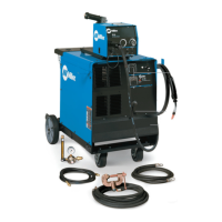
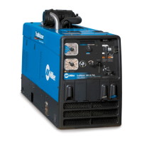
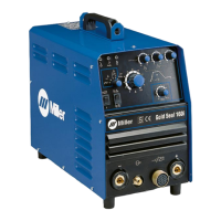
How to troubleshoot Miller GOLDSTAR 302 Welding System with no weld output and is completely inoperative?
- DDavid ChavezJul 31, 2025
If your Miller Welding System has no weld output and is completely inoperative, first ensure the line disconnect switch is in the On position. Next, check the fuse F1 and replace it if needed. Also, check and replace the line fuses if necessary, or reset the circuit breaker. Verify that the input power connections are properly connected and that the jumper link is in the correct position.