Do you have a question about the Milli-Q HX 7040 SD and is the answer not in the manual?
Policy on product improvement, information changes, and liability limitations.
Details applicable warranty and limitation of liability for products.
Copyright notice and reproduction restrictions for the document.
Lists registered trademarks and their owners.
Explains the meaning of various safety symbols used on the system.
Details electrical grounding requirements and work authorization for personnel.
Information on proper disposal of the product according to European directives.
Thanks users and advises on reading the manual for correct operation.
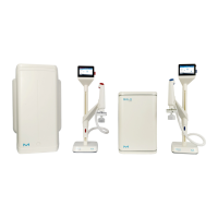
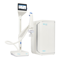
Specifies the Milli-Q HX models covered by this user manual.
Defines abbreviations like 'LC' and 'HC' used for system types.
Defines terms like 'display' and 'HMI' (Human-Machine Interface).
States that some described features may not apply to all systems.
Provides contact information for questions or requests.
Details the required feed water quality parameters for system operation.
Specifies the quality standards for water produced by the system.
Lists laboratory water quality standards the system complies with.
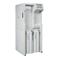
Provides detailed measurements and diagrams of the system's physical size.
Lists the dry and shipping weights for different Milli-Q HX system models.
Defines 'Shipping Weight' and 'Dry Weight' for system specifications.
Specifies the additional weight of the UF pre-filtration option.
Details the voltage requirements and power consumption for the system.
States the necessity for the electrical power source to be earth grounded.
Outlines the environmental conditions for normal system operation.
Specifies that the system is designed for indoor use only.
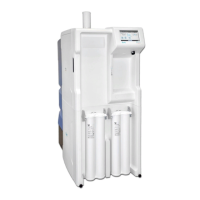
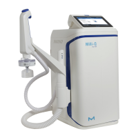
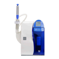
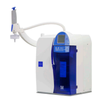
Identifies and describes major components of the water purification system.
Describes the Elix water system's role in producing Type 2 water and managing distribution.
Details the process of purifying tap water using Progard® and RO.
Explains the storage of purified water in a tank.
Describes how stored water is distributed to a loop.
Refers to the flow schematic illustrating system operations.
Explains how to access detailed component information via the Flow Schematic application.
Explains how the tank water volume influences makeup water production.
Describes the passive nature of the system's storage component.
Explains the purpose of the Ready mode for system operation.
Describes the Standby mode for stopping processes during leaks or maintenance.
Indicates that system operating modes are detailed in the Appendix.
States that the Makeup and Distribution processes operate independently.
Explains that the main system display is a touchscreen.
Identifies the Overview screen as the primary default view.
Introduces the Workspace screens for accessing system applications.
Explains navigation using icon buttons on the screen.
Describes how to access the Glance Workspace from the Overview screen.
Explains how to navigate back to the Overview screen from Workspace screens.
Details the information presented for the Makeup process on the Overview screen.
Details the information presented for the Storage portion on the Overview screen.
Details the information presented for the Distribution process on the Overview screen.
Describes the top banner containing system and connectivity information.
Explains process identifiers and operating modes shown on the Overview screen.
Describes the measure widgets and their status indicators on the Overview screen.
Details the measures displayed for the Storage process.
Explains the different operational modes for the distribution process.
Describes the Forced mode for distribution, including recirculation.
Explains the Scheduled mode for distribution based on a defined schedule.
Details the Auto-recirculation mode for the distribution loop.
Explains how the distribution panel display varies with system configuration.
Shows the distribution panel when distribution kits are installed.
Shows the distribution panel when distribution kits are not installed.
Guides users on accessing distribution modes via a button click.
Instructs users to select their desired distribution mode from available options.
Explains how the distribution panel returns to its initial view.
Describes how to monitor the status and remaining life of consumables.
Explains the display of Progard® status and remaining capacity.
Describes the status and gauge for the vent filter.
Explains the status and gauge for the loop filter.
Describes the notification and navigation bar elements on the display.
Explains the notification button, its displayed info, and color status.
Identifies the button used to navigate to the Workspace screen.
Emphasizes that Standby is for leaks or maintenance, not normal operation.
Explains that STANDBY is displayed when a process is not in READY mode.
Details how to change modes using the horizontal bars on the display.
Identifies the indicators for Makeup and Distribution modes.
Notes that the distribution panel is inactive if no distribution loop is managed.
Guides users to press the icon on the horizontal bar to change the process mode.
Explains that clicking the bar switches the process mode.
Instructs users to confirm the action to switch to the desired mode.
Describes the "PLEASE WAIT" status after mode confirmation.
Explains that tank filling and loop management become automatic when both processes are Ready.
Directs users to the Appendix for more information on operating modes.
Lists the three Workspace screens: Glance, Maintenance, and Configuration.
States that Glance Workspace provides system information applications.
Notes that returning to a workspace opens the last viewed screen.
Describes the Information Application for accessing system details.
Explains product information like manufacturing identifiers for support.
Details software and firmware versions for troubleshooting.
Describes access to customer location and address information.
Explains the Service Application for accessing service-related information.
Provides information on support key contacts like service representatives.
Details system service agreements, installation, and visit dates.
Describes the Consumables Application for viewing system consumables.
Lists details for Progard® packs including catalog number and dates.
Explains how to identify RO cartridges by type, lot, and catalog number.
Lists vent filter type, lot, catalog numbers, and dates.
Lists loop filter details including catalog number and dates.
Explains the Measures Application for viewing system measurements.
Provides information on water quality at each stage of purification.
Details monitoring of conductivity and temperature for tap water.
Explains monitoring of conductivity, temperature, and rejection outputs for the RO stage.
Details monitoring of Elix® product conductivity and temperature.
Describes monitoring of TOC, resistivity, and temperature for the distribution stage.
Explains how to view hydraulic measurements and actuator statuses.
Details tap feed pressure and external solenoid valve status.
Lists parameters for the RO stage, including pressure, flowrate, and valve statuses.
Details Elix® stage parameters, flowrate, recovery, and UV lamp status.
Describes the tank level as a parameter for the storage stage.
Explains distribution pump and dumping valve statuses.
Indicates where to find electrical measurements.
Explains that electrical values for system stages are monitored.
Describes the Flow Schematic Application for a real-time system overview.
Explains that flow schematics show actuators, measurements, and sorting options.
Describes how pressing components reveals tool tips with item information.
Provides an example of Progard pack details displayed in a tool tip.
Explains the Components Application for information on major system parts.
Lists details for RO, Distribution, and Degasser pumps.
Details catalog number, installation, and replacement dates for UV lamps.
Explains the Sanitization and Cleaning Application and its alerts.
Notes that consumable status is viewable, but replacement is in Maintenance Workspace.
Displays the last and next CL2 cleaning dates for RO membranes.
Displays the last and next pH cleaning dates for RO membranes.
Explains the History Application for viewing and exporting system data.
Details viewing historical daily measurements and system performance indicators.
Describes the daily journal of operations, including water volume and working hours.
Explains viewing event records like power status and alarms.
Describes the Distribution Schedule Application for programming the distribution loop.
Details auto-recirculation scheduling and adjustable duration.
Explains forced recirculation scheduling for the distribution loop.
Describes scheduling tank flushes to discard water from the reservoir.
Explains the Diagnostic Application for downloading log files for service.
Describes downloading the user manual via USB or Ethernet.
States that the Maintenance Workspace provides applications for maintenance and cleaning.
Explains the Service Application for parameter adjustment by qualified representatives.
Describes the Manager Application for accessing the Configuration Workspace.
Details activation, password access, and management for the Manager Application.
Explains the Consumables Application for status and launching wizards.
Compares consumable status view in Glance vs. Maintenance Workspaces.
Lists Progard® packs, Vent filter, and loop filter as consumables.
Explains the Sanitization and Cleaning Application for launching cleaning wizards.
Describes the RO membrane cleaning wizard guidance and prompts.
Explains how "Performed" and "Due" dates for cleanings are displayed.
Notes that cleaning timers can be adjusted with a Service Representative.
States the approximate durations for CL2 and pH RO membrane cleaning.
Describes the process of emptying the tank to a 0% water level.
Explains the TOC cleaning process and its duration.
States that the Configuration Workspace allows modification of system parameters.
Details access, modification capabilities, and comparison with Glance Workspace.
Explains the Information Application for modifying system information.
Describes personalization of product information like system name and location.
Explains how to find and change company name, address, and contact info.
Details adding, deleting, or modifying contacts for key personnel.
Configures system processes like makeup, distribution, recirculation, and tank functions.
Adjusts alarm thresholds, defines external signals, and manages alerts.
Manages display settings, language, sound, date/time, and network configuration.
Allows exporting and importing system configuration files for backup.
Programs the distribution loop schedule, defining behaviors and times.
Explains that some applications are on a second screen.
Guides users to change pages to access more than 9 available applications.
Explains using left/right arrows to navigate between application windows.
Notes that the first page of applications is always displayed initially.
Explains that notifications appear when the system has an Alarm or Alert.
Defines an Alert as a yellow notification for maintenance or non-critical events.
Defines an Alarm as a red notification for detected problems, system continues operation.
Defines Alarm Stop as a critical red notification that stops the system process.
Provides examples for different types of alerts and alarms.
Explains rules for acknowledging alarms and alerts and their effects.
Outlines the steps to acknowledge an alarm or alert.
Instructs to tap the notification button on the Overview screen.
Shows the Alarms and Alerts screen interface.
Guides users to click an event for detailed information and fixing instructions.
Shows the alarm information screen with details and contact advice.
Explains that alarms may trigger maintenance wizards.
States that processes return to Ready after acknowledgment and fix.
Explains that a screensaver is displayed when the system is idle.
Notes that the system operates normally and the screensaver shows main information.
Details the different visual states of the screensaver.
Describes the screensaver state when the system is in Standby.
Describes the screensaver state when the system is Ready.
Describes the screensaver state when Ready with alerts.
Describes the screensaver state when alerts are active.
Describes the screensaver state when alarms are active.
Explains how to wake the system from screensaver mode.
Explains that alerts signal the need for consumable replacement, cleaning, or sanitization.
States that wizards guide consumable replacements, cleanings, and sanitizations.
Explains various methods to launch maintenance wizards.
Refers users to the Maintenance Workspace chapter for applications.
Instructs to tap the notification button to open the Alarms and Alerts screen.
Guides users to click a message to open and follow a wizard.
Lists what the software wizard displays: location, duration, references.
Indicates the wizard shows the location of the task.
Indicates the wizard shows the estimated time for the task.
Indicates the wizard shows necessary references or parts.
Instructs users to decide whether to launch or cancel the wizard.
States that the wizard closes and alerts disappear upon completion.
Details what is needed for CL2 cleaning of RO membranes.
Lists the two available solutions for CL2 cleaning.
Describes using chlorine tablets and specific regeneration tools.
Specifies the RO Regeneration Tool for systems with one Progard Pack.
Specifies tools for systems with two Progard Packs.
Mentions RO Protect C chlorine tablets for cleaning.
Mentions using Progard Auto-clean Packs containing CL2 cleaning agent.
Details what is needed for pH cleaning of RO membranes.
Specifies the Regeneration Tool for pH cleaning with one Progard Pack.
Specifies tools for pH cleaning with two Progard Packs.
Lists the number of pH reagent pouches needed based on system type.
Notes that Service Representative selects pH cleaning type and frequency.
Lists RO cleaners, their conditioning, recommended usage, and actions.
Describes the Chlorine cleaner, its use for biofilm reduction.
Describes the RO Acid Cleaner for removing mineral scale buildup.
Describes the RO Base Cleaner for removing organic material buildup.
Notes that RO cleaning alerts and timers are adjustable based on feed water quality.
Warns against using non-specified chemicals for RO cleaning due to potential damage.
Describes the Loop Panel Assembly kit for adding Loop Filter or UV lamp.
Provides context for the task related to the loop filter.
Explains that an exhausted filter causes a pressure difference.
Outlines the procedure for checking the loop filter.
Instructs users to check pressure values on manometers.
Explains how a pressure drop indicates an exhausted filter needing replacement.
Explains that the loop filter is connected using two tri-clamps.
Provides context for the loop filter replacement task.
Outlines the step-by-step procedure for replacing the loop filter.
Instructs to set the distribution to STANDBY before replacement.
Guides users to close the two isolation valves.
Advises having a container ready to collect any spillage.
Details emptying the installed loop filter using purge valves.
Instructs users to locate the two connection clamps.
Guides users to undo the clamps by turning them anti-clockwise.
Instructs to remove the used filter or by-pass pipe, keeping clamps and gaskets.
Guides users to position the new filter between the connection clamps.
Advises to ensure the seals are correctly seated.
Guides users to close and properly position the clamps.
Instructs to tighten the clamps by turning them clockwise.
Guides users to perform an air purge of the loop filter.
Advises to open isolation valves when restarting distribution.
Warns about consequences of keeping isolation valves closed during normal operation.
Guides users to enter loop filter information in the system menu.
Outlines the final steps after replacing the loop filter.
Advises to switch distribution back on and check for leaks.
Explains the USB port's use for manual download and data export.
Describes the USB port's location and hot-pluggable nature.
Lists USB 2.0 compliance, Type A, and supported file systems.
Explains the Ethernet port for network connectivity via TCP/IP.
States that up to three users can connect, but only one can modify parameters.
Explains accessing the system interface remotely via Ethernet.
Notes that new connections are informed when the session limit is reached.
Lists the web browsers compatible with remote access.
Provides a table detailing compatible browser types and versions.
Mentions system software is licensed under GNU GPL.
Directs users to MMI for legal notices regarding software licensing.
Explains using the System Settings Application to change network configuration.
Warns against changing network settings remotely; only use the system display.
Outlines the steps to change the network configuration.
Instructs to select the System Settings Application from the Configuration Workspace.
Guides users to select the Network configuration option.
Notes that the screen displays default factory LAN settings.
Instructs to click the LAN area to access full configuration settings.
Details configuring the LAN interface, including DHCP and static IP.
Describes obtaining an IP address automatically via DHCP.
Lists fields required for static IP configuration.
Guides users to enter parameters for DHCP or static IP configuration.
Instructs users to validate the configuration by pressing the tick icon.
Prompts users to confirm the network configuration modification.
Confirms that the network configuration is changed and display returns to settings.
Explains the system is designed to remain powered for water quality.
Identifies the power switch and power outlet on the backpanel.
Warns against powering off by unplugging the cord from the outlet.
Introduces the steps for powering off the system.
Instructs to put Makeup and Distribution processes into Standby first.
Guides users to use the power switch to turn off the system.
Explains the application for programming the distribution loop schedule.
Lists the three programmable behaviors: Auto-recirculation, Recirculation, Tank Flush.
Explains schedule configuration in 30-minute slots for specific behaviors.
Instructs to open the Distribution Schedule application from Configuration workspace.
Guides users through the application interface using red bullet points.
Instructs to select a day of the week from the interface.
Guides users to choose a distribution behavior from a dropdown list.
Instructs to program a start time for the selected behavior.
Guides users to program an end time for the behavior.
Instructs to confirm choices with the '+' button and view results.
Explains how the save function becomes active to save scheduled slots.
Guides users to copy a completed day's schedule to other days.
Outlines the steps for flushing the tank.
States the prerequisite of putting Distribution processes into Standby.
Instructs to launch Sanitization & Cleaning and select Tank emptying.
Guides users to launch the tank emptying function using the specified button.
Advises checking process standby status if the tank emptying button is disabled.
Lists catalogue numbers and descriptions for system consumables.
Lists catalogue numbers for packs and filters.
Lists catalogue numbers for system cleaners.
Clarifies that 'Qty 1' refers to one unit per box.
Lists catalogue numbers for Saniclean packs and required cleaning tools.
Lists catalogue numbers and descriptions for system accessories.
Lists various accessory designations for the system.
Describes the main water sensor accessory.
Describes additional water sensor accessories.
Describes the external valve accessory.
Describes the degasser kit accessory.
Describes the external pretreatment cable accessory.
Describes the air gap accessory with 2 inlets.
Describes the flow switch for the pretreatment unit.
Describes the alarm report cable accessory.
Describes the external pressure regulator accessory.
Describes the UF pretreatment unit accessory.
Describes the installation kit for the UF pretreatment unit.
Describes the resistivity kit for high throughput measurements.
Describes the resistivity kit with boost for high throughput.
Describes the kit for resistivity boost and TOC measurement.
Describes the support kit for the loop panel assembly.
Describes the loop panel assembly kit for filter or UV lamp integration.
Describes the UV loop kit containing housing, lamp, and accessories.
Describes the cable to force water distribution regardless of schedule.
Describes the optional 1.5 bar check valve for higher pressure delivery.
Lists catalogue numbers for various Milli-Q HX system models.
Explains the meaning of various icons used on the system display interface.
Explains the function of various icons used on the system display interface.
Describes the visual status indicators for virtual system buttons.
Explains icons indicating Ethernet and USB connection status.
Introduces the chapter describing Makeup and Distribution process states.
Details the various operational modes for the Makeup process, including their uses.
Details the various operational modes for the Distribution process, including their uses.
| Type | Water Purification System |
|---|---|
| Model | Milli-Q HX 7040 SD |
| Application | Laboratory Water Purification |
| Output Water Quality | Type 1 Ultrapure Water |
| Resistivity | 18.2 MΩ·cm |
| Product Water Resistivity at 25°C | 18.2 MΩ·cm |
| TOC | < 5 ppb |
| Product Water TOC | < 5 ppb |
| Storage Tank Capacity | 40 L |
| Storage Capacity | 40 L |
| Feed Water Pressure | 1-6 bar |
| Operating Temperature | 5-35 °C |
| Feed Water Type | Potable Water |
| Purification Technology | Reverse Osmosis |
| Power Supply | 50/60 Hz |
| Installation Requirements | Indoor use, level surface |
| Operating Humidity | < 80% relative humidity |