Disk Brake Maintenance
PELLERIN MILNOR CORPORATION
3.
How to Do a Caliper Overhaul
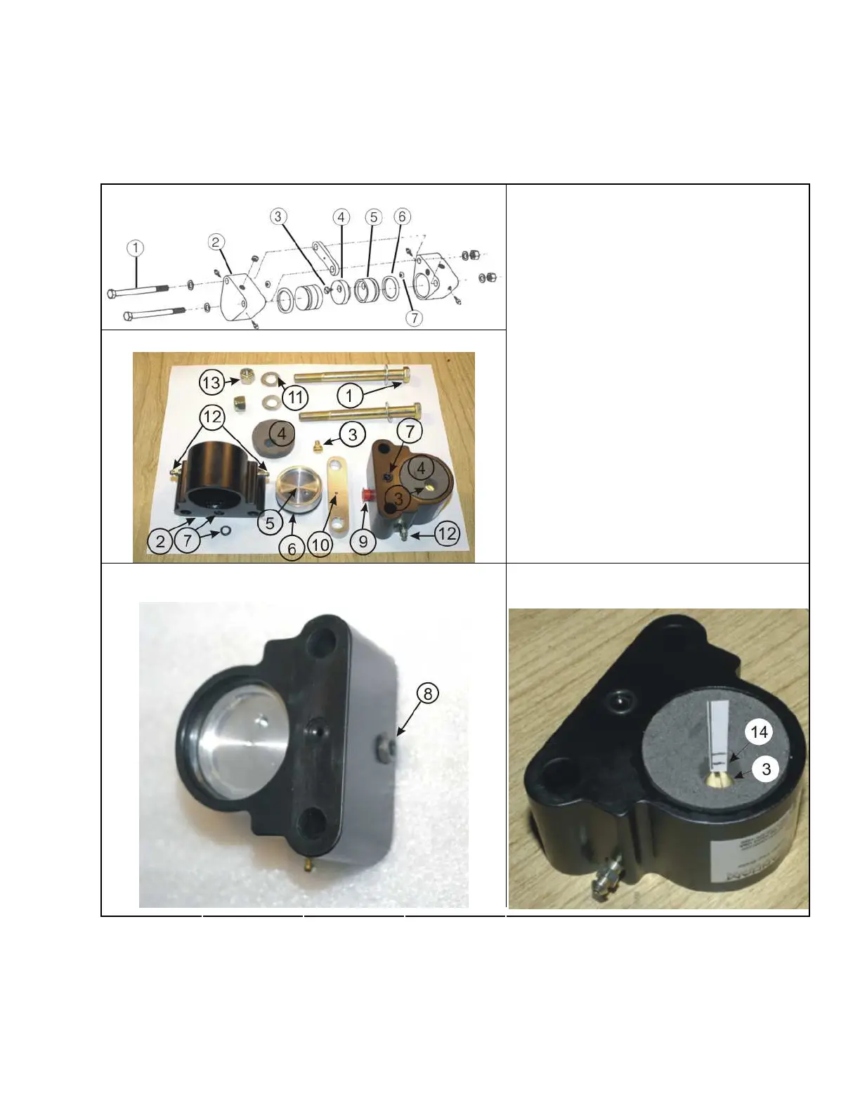
Figure 2: The Caliper Components
The Expanded View (Shows the Piston and the O-rings) Legend
The Caliper and the Pad
1. The bolts to attach the caliper (Figure 1, item
9)
2. Caliper body halves (Figure 1, item 3)
3. Brass screw
4. Friction pad
5. Piston
6. The Piston O-ring
7. The connection O-ring and its position
8. Plug for the hydraulic inlet
9. A hydraulic inlet (connected on one caliper,
a plug (item 8) on the other)
10. The hole in the spacer
11. Washer
12. One of the four valves to bleed the fluid
13. Nut
14. The pad thickness must be more than than
1/16 inches (2 mm) above item 3
Fittings for the Hydraulic Inlet Look at the pad thickness above the top of
the screw
.
Hydraulic fluid flows from one caliper to the other caliper. Fluid flows through the connection O-
rings (Figure 2, item 7) and the hole in the spacer (Figure 2, item 10). When you disconnect the
calipers, hydraulic fluid can flow from the hole at the connection O-rings. Air can get in the line.
After you connect the calipers, you must bleed the system.
82

 Loading...