Service Connections
PELLERIN MILNOR CORPORATION
2.1. Piped Inlet Specifications
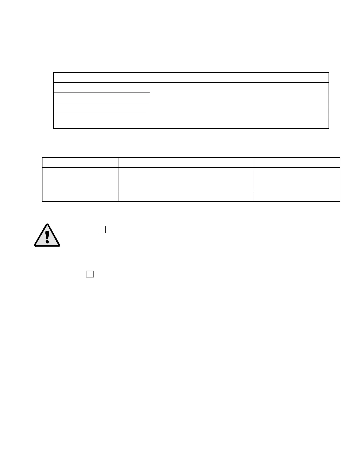
Table 1: Piped Inlets
Connection Description Source Requirements Piping Requirements, Comments
Cold water inlet
Hot water inlet
Flush water inlet
3/4" garden hose male
thread @ 10 - 75 psi
Pipe material per plumbing code
Liquid supply inlet
3/8" or 1/2"
Flexible tubing as supplied by the
chemical supplier
2.2. Piped Outlet Specifications
Table 2: Outlets
Connection Description Destination Requirements or Description Piping Specifications
Drain 3" pipe socket joint, unrestricted gravity feed to
sewer (external back pressure may extend wash
times - Do not reduce)
Rubber hose, PVC or other
approved material per
plumbing code
Vent 3"
3. Power Connections and Precautions
WARNING 3 : Electrocution and Electrical Burn Hazards—Contact with high voltage
will electrocute or burn
ou. Power switches on the machine and the control box do not eliminate
these hazards. High voltage is present at the machine unless the main machine power disconnect
is off.
• Do not service machine unless qualified and authorized.
Notice 4
: Machine Damage Hazards—Voltage fluctuations of more than 10% above or
below the specified voltage for your machine can damage electrical components, especially
motors.
• Any such conditions should be corrected prior to commissioning your machine.
The customer must furnish a remotely mounted disconnect switch with lag type fuses or circuit
breakers, and wiring between the electrical service box and the junction box on the machine. The
sizes of these fuses and wires, along with the motor fuses supplied with the machine, depend on
the machine voltage. See the fuse and wire sizing information in the schematic manual and on the
machine nameplate. See dimensional drawings in this manual for electrical connection locations.
1. Electrical connections must be made by a competent electrician.
2. See fuse and wire sizing information in the schematic manual and on the machine nameplate.
If the wire runs more than 50 feet, increase by one wire size for each additional 50 feet.
3. Only use Bussman Fusatron FRN (up to 250V), FRS (up to 600V) or similar lag fuses, the
nameplate fuse sizes must not be applied to standard fuses.
4. Stinger leg, if any, must be connected to terminal L3, never to terminals L1 or L2.
5. Make power and liquid supply electrical connections within junction boxes on the rear of the
machine.
6. Verify motor rotation (Figure 2). See the operating and trouble shooting manual for more
information. If the cylinder turns in the wrong direction, interchange the wires connected to
39