Service Connections
PELLERIN MILNOR CORPORATION
L1 and L2. Never move L3 under any circumstances. All motors are phased for proper
rotation. Never attempt to reconnect motors or the motor control devices.
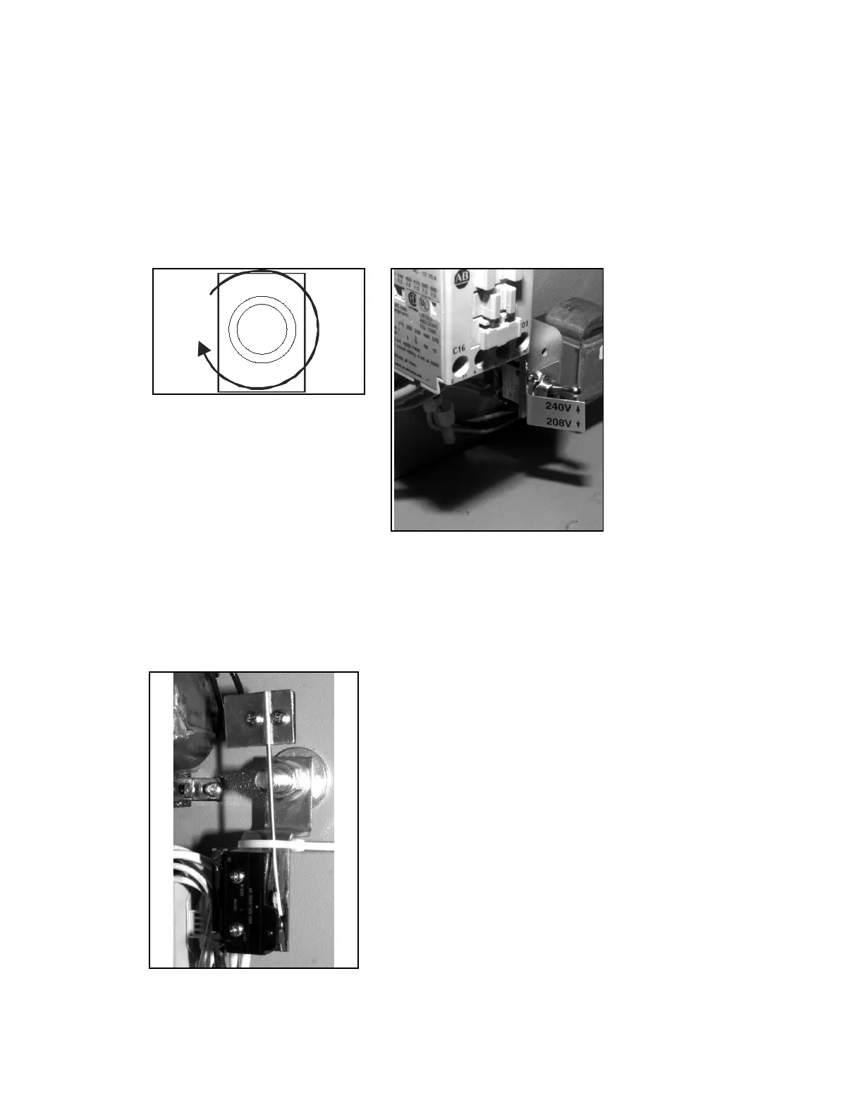
7. 240/208 volt machines are shipped set for 240 volt operation from the factory (Figure 3).
Place the line voltage switch in the 208 volt position if the supply voltage is 208 volts.
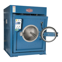
Figure 2: Correct Rotation During
Drain and Extract (when viewing
front of machine)
Figure 3: Line Voltage Switch Set
for 240 Volt Operation
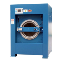
4. Remove Shipping Restraints
Remove all shipping restraints (usually marked in red). Restraints may be located behind access
panels. Restraints may include the vibration switch restraint (Figure 4).
Figure 4: Typical Vibration
Switch Showing Restraint in
Place
40