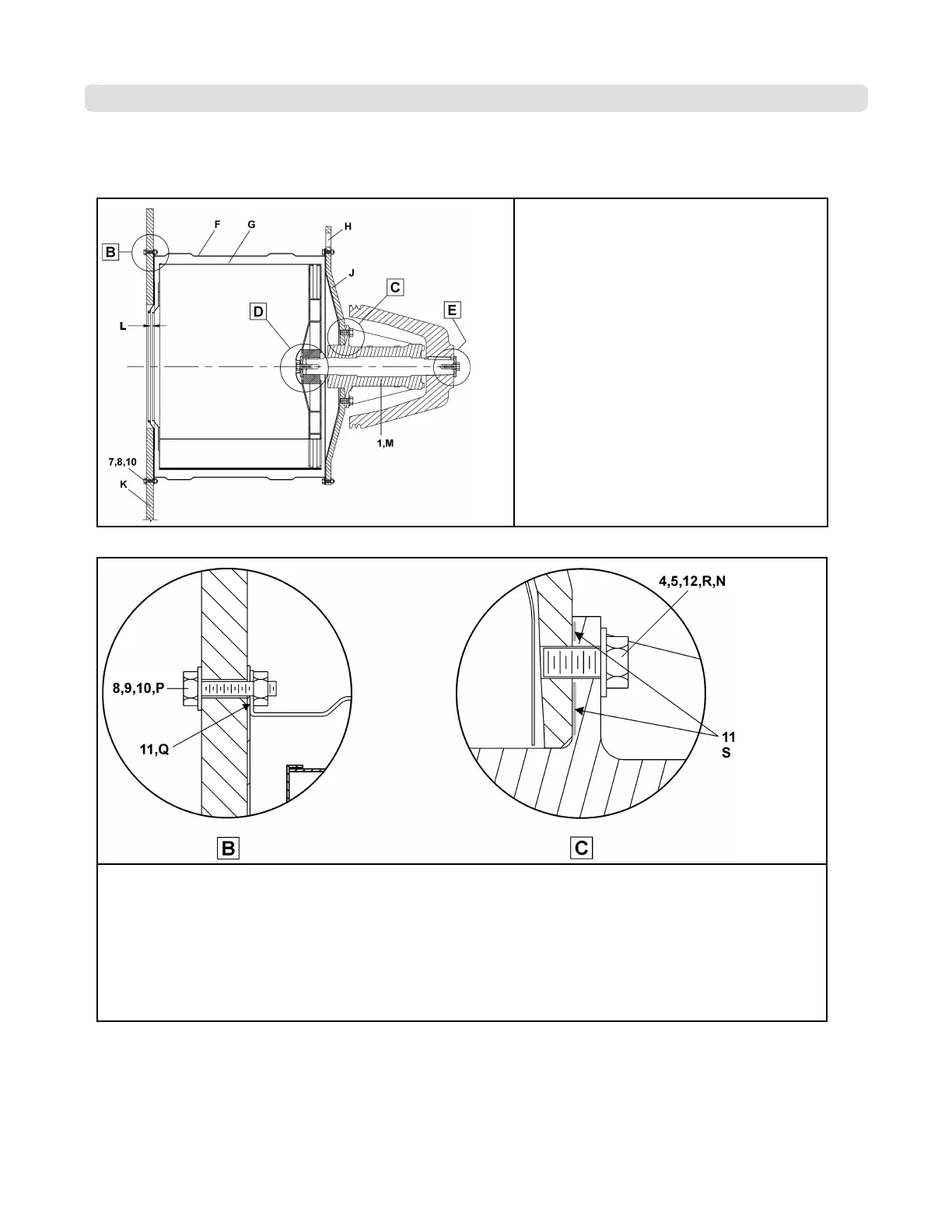
Figure 2. Shell Cross-section
Legend
B. Top connection between the shell front
and the shell side sheet
C. Connection between the shell rear and
the bearing housing
D. Connection between the cylinder rear and
the bearing housing
E. Connection between the bearing housing
and the pulley
F. Shell
G. Cylinder
H. Holes to lift the machine
J. Shell rear
K. Shell front
L. This dimension must be in this range: .25
inches [6mm] -.625 inches [15mm].
Figure 3. Shell Cross-section Details B and C
Legend
B. Connection between the shellfront and the shell
C. Connection between the shell rear and the bearing housing
N. 8 instances
P. 24 instances
Q. Apply silicone between the inner shell front and the shell, fully around the hole pattern.
R. Apply adhesive to the bolt, torque to 909 FT. LBS.
S. Apply silicone between the bearing housing and the shell rear, fully around the hole pattern.
Bearing Assembly & Installation MWF45, MWF63, MWF77
2 of 6
BPWMCB01 / 2017366A
BPWMCB01 0000161056 A.3 12/7/17 3:32 PM Released
54