INSTALLATION
The CT124 will automatically cancel the effects of long lead wires with up to 10 ohms of leadwire
resistance when used with 3-lead RTD’s. Knowing the size and length of the RTD’s leads, we can
estimate the resistance. Figure 9 lists the size of wires, their resistance per foot at 25°C, and the
maximum length each leadwire can be for 10 ohms of resistance. For proper leadwire cancellation, each
lead must have exactly the same resistance. For example, a difference of 1 ohm can mean more than
2.5°C (4.6°F) error for a 100 Ω platinum RTD, or more than 26°C (47°F) error for a 10 Ω copper RTD.
Figure 9 Leadwire Resistance Chart
Leadwire
(AWG)
Ohms/Foot
at 25°C
Maximum Length
for 10 Ohms of Resistance
18 0.0065 Ω/ft. 1538 ft.
20 0.0103 Ω/ft. 971 ft.
22 0.0165 Ω/ft. 606 ft.
24 0.0262 Ω/ft. 382 ft.
26 0.0418 Ω/ft. 239 ft.
28 0.0666 Ω/ft. 150 ft.
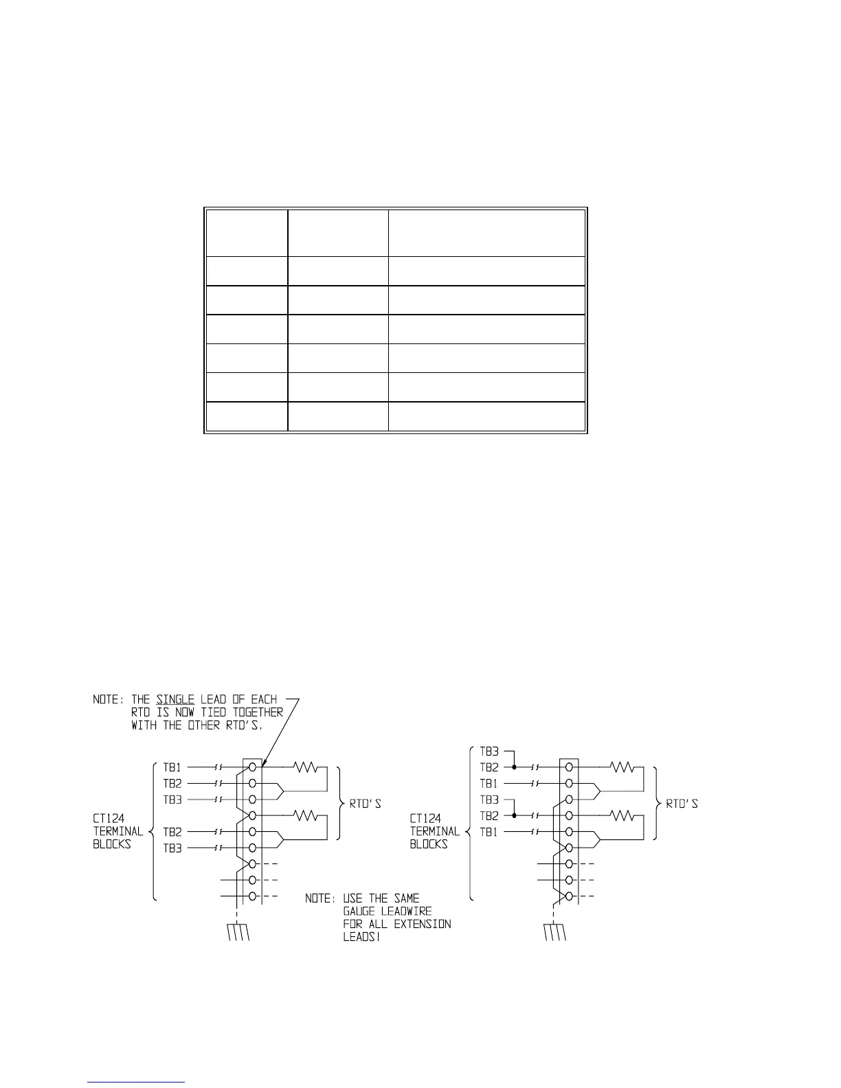
Alternative RTD Wiring Options
For the best accuracy, all 3 leads of each RTD should be brought to the CT124 as shown in Figure 8.
However, with some high voltage electric motors, the RTD’s have been prewired to a terminal block with
one of the common leads for each RTD grounded. Unless required for safety reasons, this should be
rewired with 3 individual leads for each RTD to the CT124.
Figure 10 shows 2 alternative wiring methods. With either method, ground loop currents may cause
erratic readings. If so, remove the ground connection to the CT124’s power input terminal block. Note
that option B does not provide 3-lead compensation.
OPTION A OPTION B
Figure 10 Alternative RTD Wiring Options
Minco Products, Inc. CT124 Instruction Manual
8