INSTALLATION
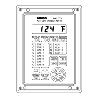
Figure 7 Dip Switch Location
RTD Wiring
Avoid routing RTD wires along with or near electrically noisy wires such as wiring to contactors, motors,
computers, etc. Electrical interference from these wires may cause instability or shifts in the CT124’s
readings. For best noise immunity, use twisted and shielded extension leadwire to the RTD’s.
The RTD wires and sensing element must be insulated from ground potential and all other voltages. Be
sure the dielectric strength rating of the RTD exceeds the voltage it will see in use, especially when
mounted in electric machinery.
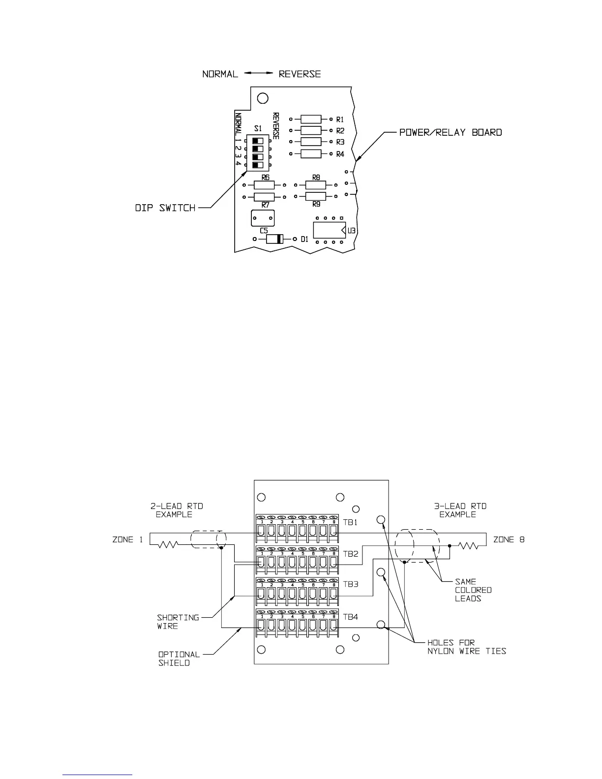
Figure 8 shows RTD wiring. For 3-lead RTD’s, connect the 2 leads of the same color to TB2 and TB3,
the odd lead to TB1. Connect 2-lead RTD’s to TB1 and TB2 with a shorting jumper wire from TB2 to
TB3. Connect shields to TB4.
Secure all wires to the connector boards with nylon cable ties in the holes provided.
Figure 8 RTD Wiring Diagram
Minco Products, Inc. CT124 Instruction Manual
7