INSTALLATION
An external power cut-off switch is not needed for safety, but would be useful if servicing inside is needed
at a later date.
The 24 VDC version is internally fused with a single .315 amp fast-blow fuse (5 x 20 mm). External
fusing is not necessary.
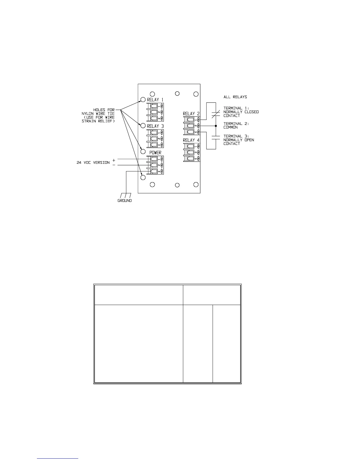
Figure 5 Relay Wiring Diagram
Relay Wiring
The relay connector board is labelled with normally open and normally closed contact symbols. This
corresponds to the unpowered or "normal" acting operating state of the relays.
In certain applications you may want the relays to be "reverse" acting. This means that if the CT124 loses
power, the relay(s) will de-energize into the tripped or alarm state. See Figure 6 for a summary of relay
states.
You can set any of the 4 relays for reverse action with dip switch S1 located on the top of the power
Figure 6 Relay States
Relay Actions Terminal Positions
1-2 2-3
NORMAL ACTING
Power on - untripped Closed Open
Power on - tripped Open Closed
Power off Closed Open
REVERSE ACTING
Power on - untripped Open Closed
Power on - tripped Closed Open
Power off Closed Open
supply (right-most) board inside the case (Figure 7). Read the safety precautions on page 2 before
removing the cover.
Minco Products, Inc. CT124 Instruction Manual
6