INSTALLATION
WIRING
Carefully read the following wiring instructions before routing the power and signal (RTD) wires to the
CT124. You must observe these guidelines in order to ensure safe, accurate, and stable operation.
No special terminals are required; just strip all wires 1/4". Maximum wire size is 14 AWG.
You may find it more convenient to unscrew the two connector boards from the rear of the case and
remove them while you are connecting the wires. In the event that the CT124 must be returned to Minco
for repair, simply disconnect the connector boards and leave the wires attached to the terminal blocks.
Power Supply Wiring
115/230 Volt Version (Standard):
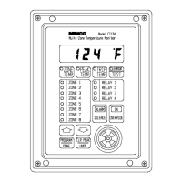
The controller is factory set for 115 VAC operation. A switch inside the case cover selects optional 230
VAC. After reading the precautions on page 2, remove the front cover. Set the switch on the right most
circuit board to 230 VAC (see Figure 3). Replace the cover.
Installation of an external power switch or circuit breaker is strongly recommended for safety and
serviceability. To replace internal fuses the power must be turned off. Also, dangerous voltages are
within easy reach if the front panel is removed while power is on.
The CT124 is internally fused with two .315 amp fast-blow fuses (5 x 20 mm). External fusing is not
necessary. The fuses are located on the power supply board (rightmost circuit board). The board must
be removed to replace the fuses.
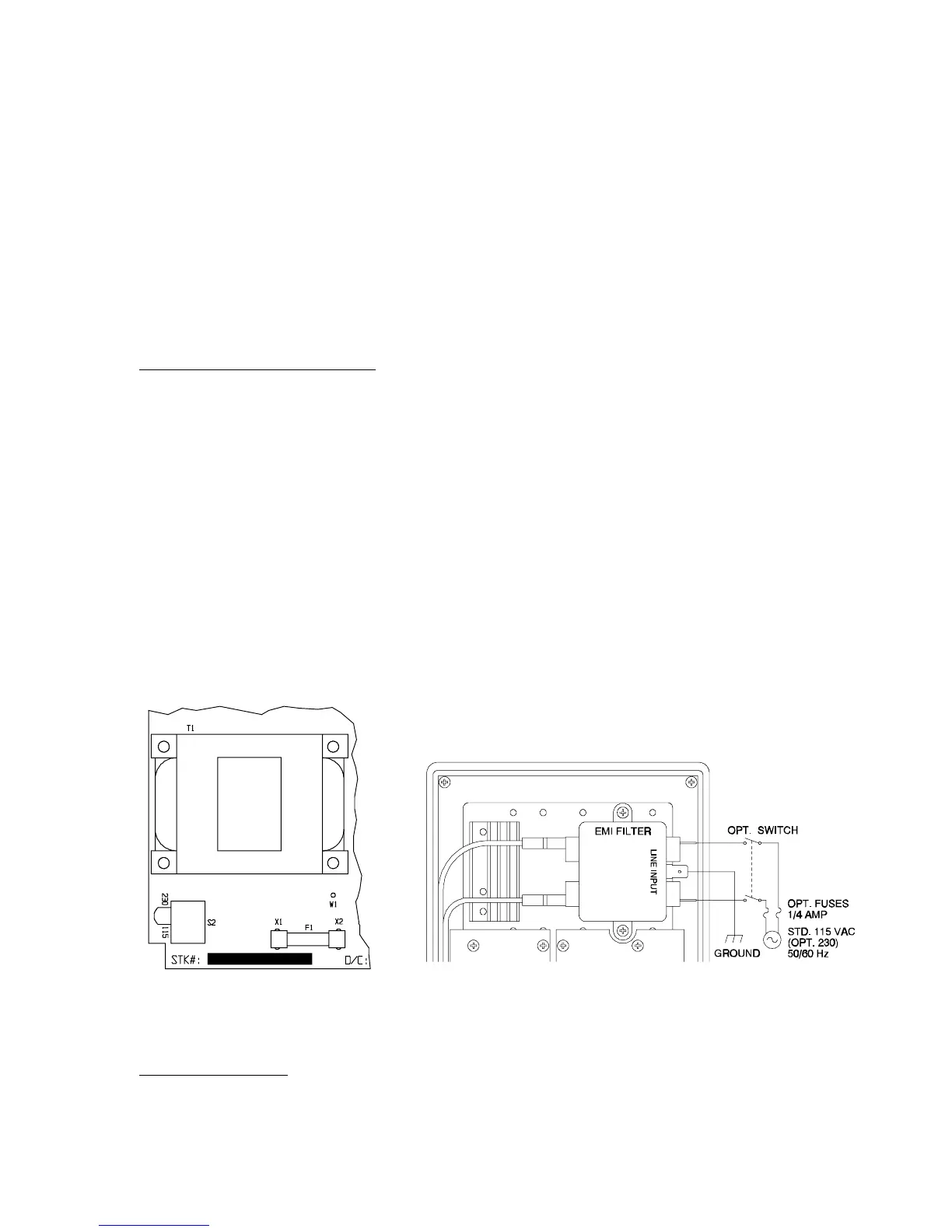
Connect power to the Line Input terminals of the power line filter on the back of the CT124. See
Figure 4 for details. Use the 1/4" quick connect terminals provided.
Figure 3 Switch Location for
115/230 VAC Operation
Figure 4 AC Power Wiring Diagram
24 Volt DC Version:
As shown in Figure 5, connect the 24 volt positive lead to terminal 1 of the power terminal block, the
negative lead to terminal 2, and chassis ground to terminal 3.
Minco Products, Inc. CT124 Instruction Manual
5