Part II General Information
Function and Performance Check 226
Adjustment Items
Control panel Gain, Depth, and iTouch
Touch screen Image Quality, Line Density, Persistence, Smooth, Sensitivity, B/C Wide,
Velocity Tag, Flow State, WF, Invert, Dual Live, Scale, Tint Map, Priority,
Baseline, Map, PW Steer, and TGC
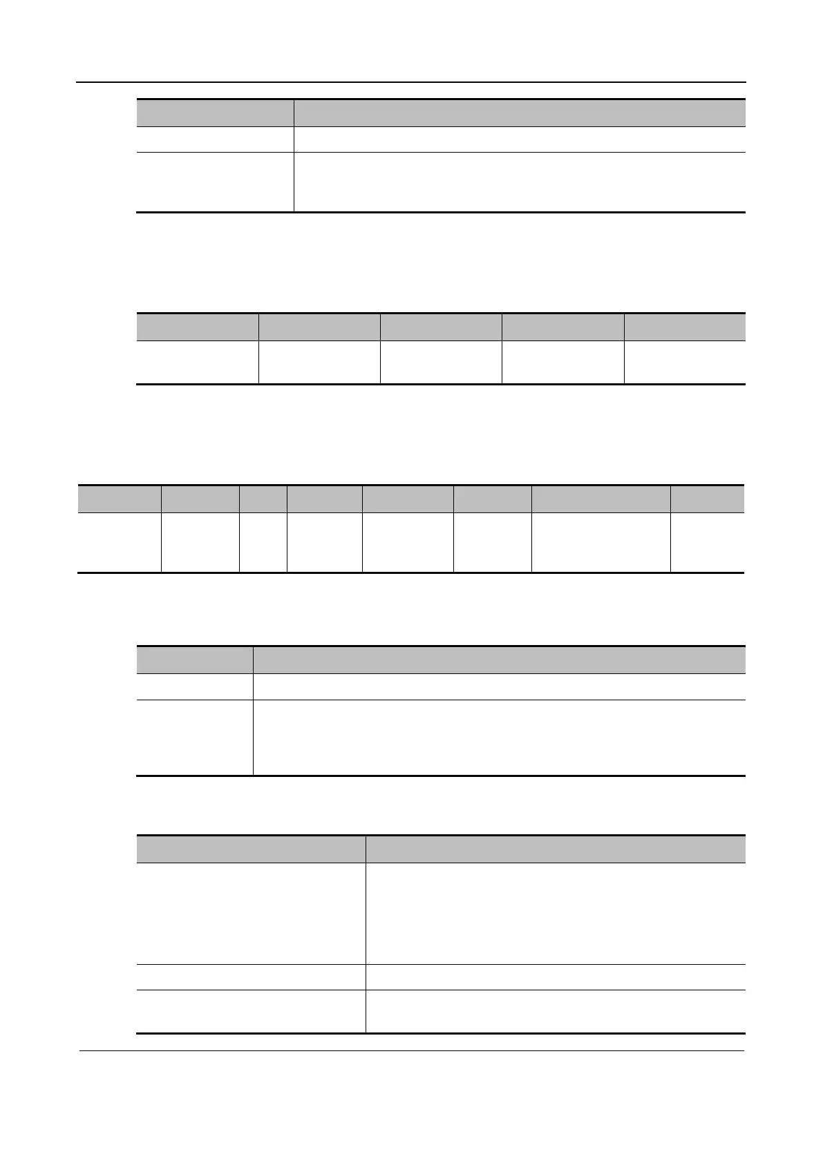
Power mode
In Power mode scan, the image parameter area on the screen displays the real-time parameter
values as follows:
Item F G WF PRF
Description Frequency Power Gain Power Filter
Pulse repetition
rate
PW/CW Doppler Mode
In PW/CW mode scan, the image parameter area on the screen shows the real-time parameter
values as follows:
Item F G WF PRF SVD SV Angle
Description Frequency Gain WF (Wall
Filter)
Pulse
repetition
rate
SV depth SV Size
(Only PW)
Angle
Parameters that can be adjusted to optimize the PW/ CW mode image are indicated in the
following.
Adjustment Items
Control panel Gain, Depth, and iTouch
Touch screen: Tint Map, HPRF, Auto Calc, Image Quality, Trace Area, Duplex/Triplex,
Dynamic Range, Impact, WF, Quick Angle, Invert, SV, Speed, Scale, Angle,
Baseline, PW Steer, Audio, Display Format, Trace, Auto Calc, T/F Res, Calc
Cycle, and A. Power
6.4.2.2 Basic Measurement
Procedure Acceptance Criteria
In B imaging mode
Press Measure.
Press Caliper.
The system enters the application measurement mode.
The system enters the normal measurement mode.
Click any one or two measurement items (such as length and
area), and the measurement or calculation results are displayed
below the image in real time.
Press Caliper or Measure again. The system exits the corresponding measurement state.
Perform similar operations in other
imaging modes.
The application measurement function maps different
application software packages. Perform operations selectively.