Note:
If required, the additional lift o protection PR 6012/53 or PR 6012/54 can be
mounted (see Chapter 3.3).
This does not apply for PR 6012/01.
CAUTION
Do not damage the membrane on the bottom of the load cell.
Carefully insert the load cell.
5.4 Check mounting
When all mounting kits have been installed, check them for proper mounting.
In particular, force shunts should be avoided.
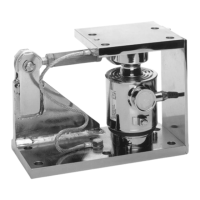
Example: PR 6012/31
5. Position the lifting gear on the weighing object.
6. Remove the auxiliary mounting plate (1).
7. Use the appropriate lifting gear to lift the weighing object so that the load cell (9) can
be inserted with the load disc (10).
8. Load the load cell slowly. It is essential to ensure that the load cell is vertical and not
jammed after loading.
9. If necessary, re-adjust the upper plate (4) and the lower plate (7).
10. If necessary, adjust the additional lift-o protection (see Chapter 3.3).
11. Connect an equipotential bonding conductor (6) (supplied with the load cell) between
the upper plate (4) and the lower plate (7).
5 Installation Mini FLEX and Mini FLEXLOCK mounting kits PR 6012/01, ../31, ../41
Minebea Intec EN-19