1
1. Name and function of each point
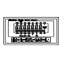
1-1. Front panel
(1) Unit display section
The set measuring unit is displayed.
[○] lights at the unit display section at the stand-by condition (The load display has been turned off
while energized)
(2) Load display section
It displays [Gross/Net value], [Over] and [Error].
Also it displays the condition or the setting value in preceding the various setting.
(3) Condition display section 1
It displays the condition of CSD-903.
STABLE It lights when the measured data is steady.
PRESET TARE It blinks while setting a preset tare weight cancellation.
It lights when a preset tare weight cancellation is set.
TARE It lights when the tare weight cancellation is executed.
GROSS It lights when the load display is gross value.
NET It lights when the load display is net value.
ZERO It lights when the displayed load value is zero, and within ±1/4 of a scale interval.
HOLD It lights when HOLD function is active.
ERROR It lights when the output of ERROR signal outputs.
(1) Unit display section
(9) PRESET TARE ke
(8) ACCUM. ke
(7) SET ke
(6) ON/OFF ke
(2) Load display section
(3) Condition display section 1
(5) Sub display section
(4) Condition display section 2
(13) F key
(12) ZERO key
(11) NET/GROSS key
(10) TARE key
 Loading...