Do you have a question about the Minebea CSD-701B and is the answer not in the manual?
Specifies environmental conditions for instrument placement, including temperature and humidity.
Lists locations to avoid for instrument installation to prevent faults.
Details physical dimensions and panel cut sizes for instrument installation.
Discusses protection against humidity and dust using panel mount gasket.
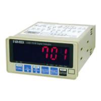
Lists key features such as compact size and A/Z/peak hold functions.
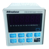
Explains front panel components like display, status indicators, and keys.
Describes rear panel terminal board and optional interface slots.
Specifies operating temperature and humidity ranges.
Lists environments unsuitable for instrument installation.
Provides outline dimensions and panel cut size details.
Details dust and water-proof installation using a gasket.
Identifies terminal numbers, descriptions, and applications.
Provides crucial precautions for making electrical connections.
Details wiring for connecting load cells and similar transducers.
Explains wiring for external control signals like ZERO and HOLD.
Describes wiring for S1 and S2 contact outputs.
Covers power supply and grounding connections.
Details wiring for voltage and current analog outputs.
Steps required before starting calibration.
Overview of different calibration methods.
Procedure for setting span after zeroing the load cell.
Method for calibrating both zero and span points.
Calibration using actual load conditions.
Fine-tuning the zero point of the instrument.
Fine-tuning the span of the instrument.
Procedure to re-register the zero point only.
Guidance on selecting the appropriate calibration method.
Calibration steps for new instruments.
Procedures for re-calibration.
How to prevent further calibration.
Explains operations using the FUNC key.
Explains operations using the SHIFT key.
SHIFT key usage in measurement mode.
SHIFT key usage in other modes.
Explains operations using the ENTER key.
ENTER key usage in measurement mode.
ENTER key usage in other modes.
Explains operations using the RESET key.
RESET key usage in measurement mode.
RESET key usage in other modes.
Explains operations using the HOLD key.
HOLD key usage in measurement mode.
HOLD key usage in other modes.
Explains operations using the ENTER key.
Details external control inputs and contact outputs.
Explains input signals like ZERO, HOLD, PEAK/TRACK, RESET.
Describes contact outputs S1 and S2.
Provides equivalent circuits for input and output sections.
Explains comparator functions S1 and S2.
How to enable or disable comparators.
Procedures for changing comparator set values.
Explains comparator operation modes (e.g., contact ON above/below set value).
How to select comparison targets like PEAK/Net weight.
Setting comparator hysteresis for chatter prevention.
Instructions for using the digital filter.
Details on digital filter settings and their effects.
Function to compensate for slow zero drift.
Explanation of the zero tracking function.
How to configure zero tracking parameters.
Procedure to cancel zero tracking compensation.
Function to stabilize the load display during load variations.
Explanation of the stabilized filter's purpose.
How to set up the stabilized filter parameters.
Switching between Peak and A/Z functions.
Instructions for using the peak hold function.
Various display settings and options.
Setting display update frequency.
Adjusting decimal point position.
Setting the display range for load values.
Choosing what the HOLD function monitors.
Selecting bridge power supply voltage.
Using the tare weight cancellation function.
Function to set the zero point.
Enabling or disabling front panel keys.
Function to display a set CHECK value.
Instructions for analog output configuration.
Scaling the analog output range.
Fine-tuning analog output with actual load.
Selecting the data source for analog output.
Overview of data storage in RAM and EEPROM.
Setting to prevent calibration.
How to perform device self-checks.
Step-by-step guide for using the check mode.
Real-time monitoring of input values.
Steps to enter and set function parameters.
Detailed descriptions of various function parameters (F-codes).
Details on the current output option.
Functions associated with current output.
Technical specifications for the current output option.
Details on the BCD output option.
Functions associated with BCD output.
Technical specifications for the BCD output option.
Timing diagrams for BCD output signals.
Describes output states for BCD signals.
Setting PC output logic and width.
Details of the RS-232C communication interface.
Functions related to RS-232C interface.
Technical specifications for RS-232C interface.
Methods for data transfer via RS-232C.
RS-232C connector pin assignments.
Data format for RS-232C communication.
Handling communication errors in RS-232C.
Details of the RS-422 communication interface.
Functions related to RS-422 interface.
Technical specifications for RS-422 interface.
Data transmission via RS-422.
RS-422 connector pin assignments and wiring.
Data format for RS-422 communication.
Handling communication errors in RS-422.
Details of the serial communication interface.
Functions related to the serial interface.
Technical specifications for the serial interface.
Connecting and equivalent circuit for serial interface.
Data format for serial interface communication.
Explanation of serial data format bits.
Explanation of serial output types.
Details for the DC12V power supply option.
Terminal board layout for DC12V supply.
Connecting DC12V power and grounding.
Details for the DC24V power supply option.
Terminal board layout for DC24V supply.
Connecting DC24V power and grounding.
Physical dimensions and panel cut-out details.
Step-by-step guide to diagnose and resolve issues.
Troubleshooting specific optional modules.
Lists error codes, contents, and remedies.
Technical specifications for the analog input/output.
Functionality of front panel keys.
Specifications for external control inputs.
Details on comparator settings and capabilities.
Specifications for contact outputs.
Summary of the instrument's various functions.
Overall operating parameters like temperature, humidity, power.
Default settings and specifications upon shipment.
List of included accessories.
List of available optional modules.
Specifications for the current output option.
Specifications for the BCD output option.
Specifications for the RS-232C interface option.
Specifications for the RS-422 interface option.
Specifications for the serial interface option.
Specifications for power supply voltage options.
Physical dimensions and panel cut-out details.
Details the warranty period and contact information.
Information and steps for requesting repairs.
Step-by-step guide for replacing the instrument's fuse.
Table showing 7-segment display character patterns.
Reference table for initial and customer function settings.
| Operating Voltage | 3.3V |
|---|---|
| Operating Temperature | -20°C to 70°C |
| Storage Temperature | -30°C ~ 80°C |
| Size | 7.0 inch |
| Interface | I2C |