89
9−2. BCD output
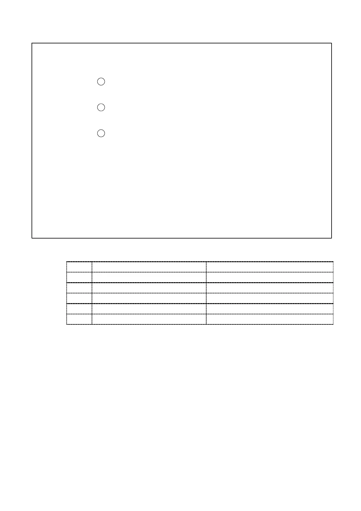
Warning ● When power is ON for the instrument with the external HOLD signal
shorted, the BCD output will be as follows:
1
Even when the Display is targeted for the HOLD with the F−10,
BCD outputs “00000” if the target for BCD output is set as Display.
2
When the BCD output is assumed to be the target of HOLD with
the F−10, BCD output outputs “00000”.
3
Other than the case above ① and ②, the present load value will
output after “00000” has output.
● In other than the Measurement mode, the BCD output will not be
renewed. In due course, the “ERROR” for the BCD output won’t be
ON in other than the mode of the Measurement mode, so care should
be taken fully.
● When the CHECK switch is applied, pay attention to the following
point. By the ON operation of CHECK, the “OL” error display (BCD
output is OVR.) might be shown.
9−2−1. Related function
F−40 Setting the target of BCD output TRACK/Gross weight, PEAK/Net weight
F−41 Setting output logic for BCD data
Negative logic, Positive logic
F−42 Setting output logic for BCD polarity
Negative logic, Positive logic
F−43 Setting output logic for BCD flag
Negative logic, Positive logic
F−44 Setting output logic for BCD P.C.
Negative logic, Positive logic
F−45 Setting the width of BCD P.C. 25 ms, 125 ms
9−2−2. Specifications for BCD output
(1) Output logic
Relative function Negative logic, Positive logic can be changeable by the related
functions F−41, F−42 and F−43.
(2) Output data
BCD 5 digits parallel output
POL.(Polarity) ON at minus, and output OFF at plus.
P.C.(Print command)
ERROR
OVR.(Over)
(3) Input data
BCD−ENABLE Compulsive OFF for the related output with BCD
(High−impedance)