111
9−6. Power supply voltage DC12 V(CSD701B−P66)
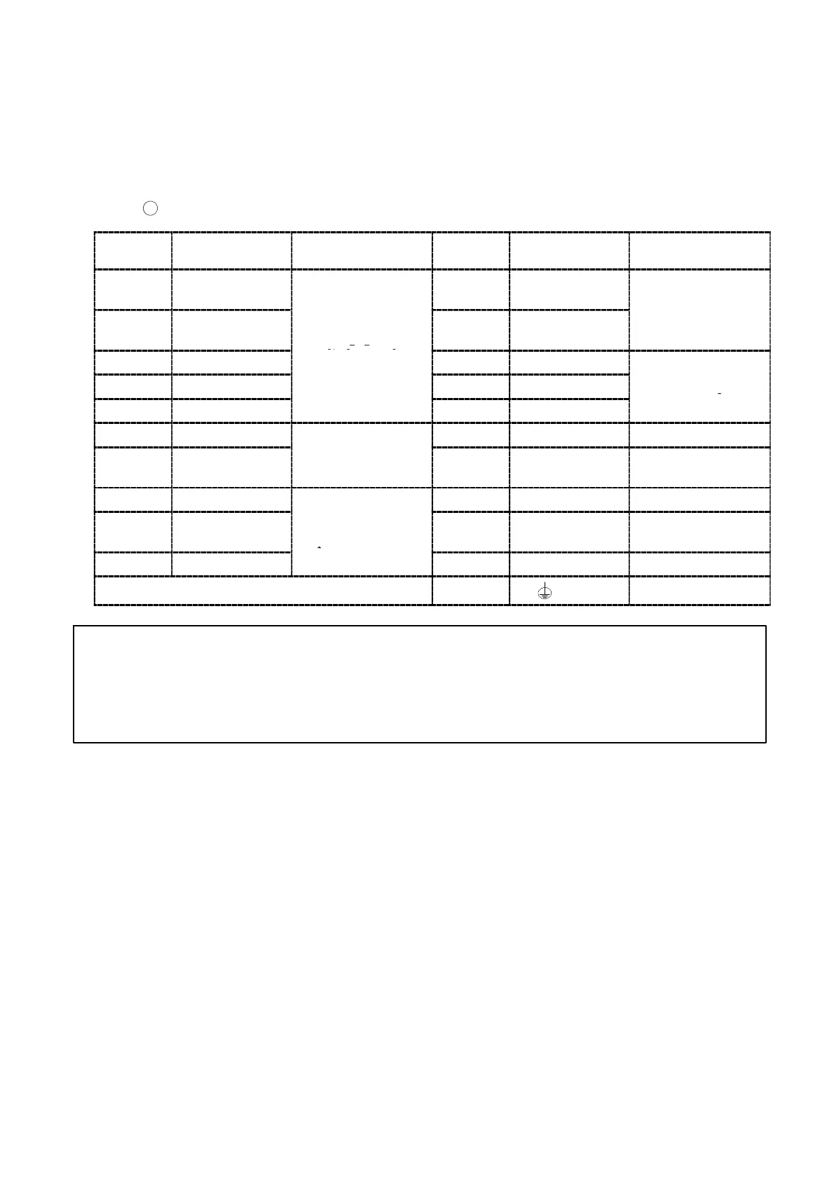
9−6−1. Layout of the terminal boards
There is one terminal board containing 21 point of terminals in the panel.
Layout of terminal boards when the power supply voltage is DC12 V are shown in the following
figure.:
1
Terminal board(21P)
Terminal
No.
Descriptions Applications
Terminal
No.
Descriptions Applications
1 A 11
PEAK/TRACK
or A/Z
External control
2 B
Strain gage
12
RESET or A/Z
OFF
input
3 C
applied transducer
13 COM.2
4 D 14 S1
Contact output
5 E 15 S2
6 A−OUT + 16 F. G Frame ground
7 A−OUT −
Analog output
17 SOURCE
DC0 V power
supply
8 COM.1 18 N.C.
9 ZERO
External control
input
19 SOURCE
DC+12 V power
supply
10 HOLD
20 N.C.
21 Ground
● The COM.1(Terminal No.8) and COM.2(Terminal No.13) are isolated.
● Please refer to clause 4−2 for notes concerning connecting wires.
● The power supply is DC12 V(DC10 V to DC15 V).