Klemmplan
Circuit diagram
Hako Jonas 900 E
Gültig ab: Mai 2004
Valid from: May 2004
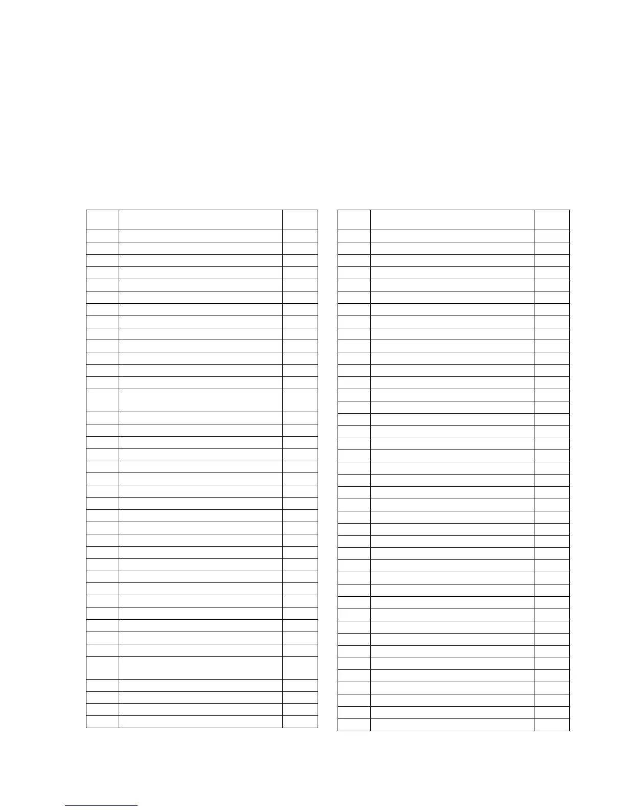
Ref. Designation
Curr.
path
A1 Control unit /1.8
F1 63A fuse, control unit power module /1.8
F2 20A pre-fuse U switched 1 and 2 /1.15
F3 10A fuse control unit controlling /1.25
F4 5A fuse control panel indicators, shaking /2.24
F5 Fuse reserve /2.17
F6 5A fuse LDS indication /2.14
F7 5A fuse LDS /2.12
F11 30A fuse shaking motor /2.26
F12 60A fuse main motor /2.4
G1 24V battery /1.2
H1 Parking brake pilot lamp (prepared, not fitted) /2.22
H2 Pilot lamp LDS battery okay /2.14
H3
Pilot lamp control unit malfunction
(prepared, not fitted)
/1.12
H4 Pilot lamp LDS battery discharged /2.15
H6 Buzzer (prepared, not fitted) /1.24
K1 Relay Multimode /2.11
K2 Relay main motor /2.7
K3 Relay /1.22
K5 Relay /2.24
K5 Impulse relay shaking (option) /2.20
M1 Drive motor /1.5
M1.S1 Thermal contactor drive motor /1.6
M2 Main motor /2.4
M2.S1 Thermal contactor main motor /2.7
M3 Shaking motor /2.25
P1 Hourmeter /2.19
R1 Drive rheostat /1.18
R2 7kS resistor /2.14
S1 Key switch /1.15
S2 Micro-switch reverse ride /1.18
S3 Micro-switch forward ride /1.16
S5 Seat switch /1.20
S6 Micro-switch main motor /2.7
S7 Service/parking brake switch
(optional fitting possible)
/2.22
S10 Micro-switch shaking /2.24
Z1 LDS /2.12
Ref. Designation
Curr.
path