Do you have a question about the Mirage B 2518 G and is the answer not in the manual?
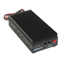
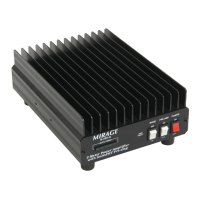
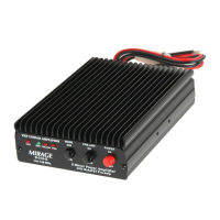
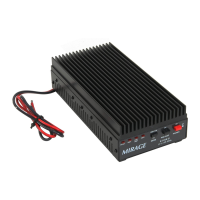
Ensures optimal performance and longevity by managing operational temperatures and heatsink cooling.
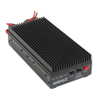
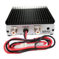
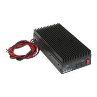
Details critical DC power connections, fuse requirements, and proper grounding for safety and performance.
Specifies connector types, cable quality, and length considerations for RF and control connections.
Provides guidelines for selecting location and wiring when installing the amplifier in a mobile environment.
Offers recommendations for mounting and power supply considerations in stationary installations.
Outlines specific requirements and considerations for using the amplifier in a repeater setup.
Specifies recommended drive power levels from the radio or exciter for optimal performance and safety.
Explains duty cycle limitations based on temperature, mounting, and operating power.
Describes the automatic RF sensing system and manual control for transmit/receive switching.
Details the proper coaxial cable connections between the exciter and the amplifier.
Sets drive power limits for FM, CW, and FSK to prevent overdrive and ensure transistor safety.
Discusses duty cycle for CW and FM based on operating conditions and temperature.
Guides on selecting feedlines and antennas, emphasizing SWR and reflected power limits.
Explains linearity issues like splatter and distortion, and how drive power affects them.
Details proper drive power settings for SSB/AM to achieve linear amplification and avoid distortion.
Defines duty cycle for SSB/AM based on temperature, mounting, and operating power.
Describes the internal RF sensing system and front-panel MODE switch for transmit/receive control.
Specifies the maximum clean linear SSB service power output and power source requirements.
Provides guidelines for antenna and feedline selection for optimal SWR and linearity.
Discusses the preamplifier's noise figure and its impact on signal detection and SNR.
Explains IMD and how to prevent receiver overload or preamplifier damage from strong signals.
Troubleshooting steps for when the amplifier fails to transmit or receive signals.
Checks for power issues, fuses, and basic wiring problems when the unit is unresponsive.
Diagnoses issues when the unit transmits but does not improve receive signal strength.
Troubleshooting steps for when the unit receives but does not amplify transmitted signals.
Addresses causes of the FAULT light, such as excessive drive power or high SWR.
Identifies potential causes for relay chattering, like reversed leads or low drive power.
Provides contact information and advice for obtaining technical support.
Details how to order replacement parts directly from the manufacturer.