EasyManua.ls Logo

Mirage B 5018 G - User Manual

Mirage B 5018 G
17 pages
Print Icon
To Next Page IconTo Next Page
Loading...
1
Mirage B 5018 G
This compact, rugged, VHF RF power amplifier greatly improves signal-quality and
range. This unit contains a low-noise GAsFET receiving amplifier, a 160-watt power
amplifier, and associated control and protection circuitry.
This amplifier operates from any well-filtered direct-current 11-15 volt power source
capable of supplying 30 amperes under full-load. The power source must be either
negative grounded or totally ground independent.
Warning, never use this unit with:
1.) positive-ground supplies
2.) vehicles having positive-ground batteries
3.) power sources exceeding 16 volts
Always fuse power leads at the battery with 30-ampere fast-blow fuses.
This amplifier has the following important features:
1.) Automatic RF actuated transmit and receive switching or manual switching
2.) Active bias for greatly improved SSB linearity
3.) Low-noise GAsFET receive preamplifier
4.) True push-pull circuitry and clean RF layout for excellent stability
5.) Excess SWR and overdrive protection
6.) Remote control capabilities
Question and Answer IconNeed help?

Do you have a question about the Mirage B 5018 G and is the answer not in the manual?

Overview

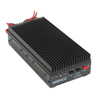
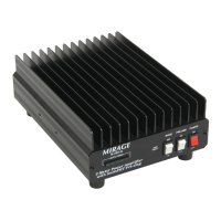
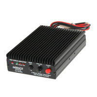
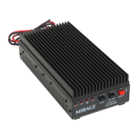
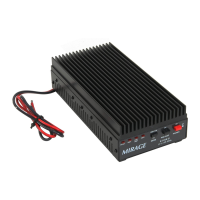
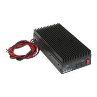
The Mirage B 5018 G is a compact, rugged VHF RF power amplifier designed to enhance signal quality and range. It incorporates a low-noise GaAsFET receiving amplifier and a 160-watt power amplifier, along with associated control and protection circuitry.

Power Requirements and Safety:

The amplifier operates from a well-filtered 11-15 Vdc power source capable of supplying 30 amperes under full load. The power source must be either negative-grounded or totally ground-independent. It is crucial to fuse the red positive lead at the battery or power supply with a 30-ampere fast-blow fuse to prevent wiring fires. The red lead must always be positive, and the black lead should connect to the vehicle's chassis with a good solid connection. The manual explicitly warns against using the unit with positive-ground supplies, vehicles with positive-ground batteries, or power sources exceeding 16 volts.

Key Features:

  • Automatic RF Actuated Switching: The unit features automatic switching between transmit and receive modes based on RF signals, or it can be manually switched.
  • Active Bias: This system provides greatly improved SSB linearity by forcing the bias voltage to a fixed level, which is superior to conventional resistor/shunt-diode bias in maintaining operating bias as drive power, temperature, and supply voltage vary.
  • Low-Noise GaAsFET Receive Preamplifier: Improves weak signals with a noise figure of just over 1 dB and a maximum gain of about 14 dB. Gain is selectable via internal jumpers (approximately 14, 8, and 5 dB).
  • True Push-Pull Circuitry and Clean RF Layout: Ensures excellent stability.
  • Excess SWR and Overdrive Protection: Protects the amplifier from damage due to high reflected power or excessive input power. The FAULT light illuminates when drive power exceeds 50 watts or reflected power exceeds 20 watts, indicating that protection circuits have locked on.
  • Remote Control Capabilities: Allows for flexible installation and operation.

Mounting Considerations:

For optimal performance and longevity, the amplifier should be mounted in a cool, well-ventilated area, ideally with the heatsink fins oriented vertically to facilitate natural convection. Avoid confined, hot, damp, or dusty locations, and areas subject to mechanical shock or vibration. Ambient temperatures should not exceed 110°F (43°C). If the heatsink becomes uncomfortable to touch (above 140°F), additional cooling, such as a fan (Mirage FK-18 cooling kit), may be necessary.

Power Wiring Details:

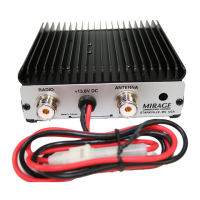
The red power lead connects to the positive 12-15 Vdc battery or power supply terminal, and the black lead is the negative lead, grounded internally and common with the metal case and connector grounds. To minimize voltage drop and maximize power output, heavy gauge power and ground leads should be kept as short as possible. The manual provides a chart detailing maximum cable lengths for different AWG sizes to limit voltage drop to 0.5 volts or less at 30 amperes.

RF and Control Cables:

The RADIO connector is a SO-239 (UHF Female) type, matched for 50-ohms. The input cable can be any reasonable length of good-quality 50-ohm coaxial cable. The ANTENNA connector is also a SO-239 (UHF Female), designed for a 50-ohm load with a VSWR under 2:1. The output cable must safely handle 200 watts at 150 MHz. Control cables, including the RELAY jack (phono female connector for manual transmit mode activation), can be any reasonable length due to low current.

Mobile Mounting:

Avoid mounting in excessively warm, unventilated, damp, or wet locations. The best location is a well-ventilated area within the passenger compartment. Engine compartments should never be used. Ensure wiring is not pinched or cut. All power leads must be fused at the battery (30-ampere fast-blow fuse). The negative lead should be grounded to the vehicle's sheet metal.

Home or Fixed Installations:

Mount in a cool, circulating air location, ideally with vertical heatsink fins. Consider adding a cooling fan for extended duty. The amplifier should be mounted close to the power supply, which should be well-filtered, voltage-regulated (no more than 15 Vdc), and have internal current limiting or a fuse at 35 amperes. Ground the unit's case to the station ground buss with a heavy short lead.

Repeater Mounting:

For repeater use, output power must be reduced to 50 watts (approximately 6 watts of drive power), and the cooling system must be augmented with forced air (Mirage FK-18 kit). Consult the factory before using for repeater applications.

Radio or Exciter Compatibility:

The amplifier works with exciters or radios operating between 140 and 150 MHz.

  • Drive Level: Input power should be between ½ and 50 watts. Do not exceed 50 watts on FM, 4 watts carrier on AM, or 20 watts PEP on SSB (about 6 watts average power).
  • Duty Cycle: Primarily limited by heatsink temperature. Increased power output and ambient temperature necessitate better cooling.
  • T/R Control or "Keying": An internal RF sensing system automatically disconnects the pre-amplifier and switches to transmit mode when the POWER switch is ON. The rear-panel RELAY jack can manually force transmit mode when pulled low (grounded). A front-panel MODE switch activates a hang-delay timer for SSB/CW operation (factory set to 1 second).

FM, CW, and Non-Linear Modes:

These modes (CW, FM, FSK) do not rely on distortion-free amplitude changes. The amplifier can "gain compress" or "flat-top" without affecting signal quality or bandwidth, allowing higher output levels without detectable signal bandwidth changes.

  • Drive Power: Limited by transistor power ratings and heatsink temperature. Transistors can safely accept 50 watts of drive, yielding approximately 160 watts carrier output.
  • Duty Cycle: Maximum output power is 160 watts ICAS, providing a 33% long-term duty cycle without overheating (not exceeding 5 minutes total transmitting time without 10 minutes resting time). The safe maximum heatsink temperature is 140°F.
  • Feedlines and Antennas: Works with any antenna as long as SWR at the output is less than 2:1. Never exceed 20 watts maximum reflected power.

SSB and Linear Modes:

SSB and AM operation require linear amplification to prevent "splatter" (mixing products that increase signal bandwidth). Solid-state amplifiers experience gain compression before saturation.

  • Peak Output Power: Maximum SSB peak power is approximately 110 watts, corresponding to an average power of 25 to 50 watts depending on voice and compression. Unmodulated AM carrier output should not exceed 25 watts, with peak envelope power not exceeding 100 watts.
  • Splatter and Distortion: Minimized by the active-bias system and by reducing drive power. Drive power should allow output power peaks to reach approximately 2/3 of the saturated output power (110 watts PEP for good linearity).
  • Duty Cycle: At 110 watts PEP, the amplifier normally provides a 100% duty cycle without overheating.

Receiving Preamplifier (Pre-Amp):

The internal preamplifier "boosts" weak signals with a noise figure of just over 1 dB and up to 14 dB gain. Gain is selectable via internal jumpers (5, 8, or 14 dB). In congested areas, it may be advisable to NOT use the pre-amp to reduce receiver overloading. A lower noise-figure amplifier is rarely necessary for terrestrial communications.

  • Intermodulation (IMD) Products: Efforts were made to make the preamplifier immune to overload. If paging or commercial transmitters appear in the receiver when using the preamplifier, try turning it off. Always use the lowest necessary gain setting.
  • Warning: Never connect the unit backwards (radio to ANTENNA, antenna to RADIO) as this can damage the preamplifier. Do not use the preamplifier if the antenna is near other transmitters.

Troubleshooting (In Case of Difficulties):

  • Does Not Transmit or Receive at All: Check power wiring (section 1.2) and RF connections (section 1.3). Test the radio with a barrel connector instead of the amplifier.
  • Nothing Lights or Seems to Work: Check power wiring and fuses (including the internal fuse).
  • Transmits OK, Does Not Amplify Receive: If the Preamp light illuminates but signals are not improved, the preamplifier may be defective. If the XMIT light remains on during receive, check CONTROL or RELAY wiring.
  • Receives OK, Does Not Amplify Transmit: Check if the radio transmits OK without the amplifier. Verify SWR both in-line and out-of-line.
  • Continuously Trips FAULT Light: Check drive power (especially PEAK power, ensuring it's below 50 watts) and reflected power (below 20 watts, SWR below 2:1). Look for bad cable connections.
  • Relay Chatters or Clicks Off and On: Indicates reversed RADIO and ANTENNA leads or drive power too low (under ½ watt).

Technical Assistance and Ordering Parts:

Technical assistance is available Monday through Friday from 8:00 a.m. to 4:30 p.m. Central Time by calling 662-323-8287. When contacting, have the model number, serial number, and radio/power meter information ready. Parts can be ordered directly from Mirage by phone (662-323-8287), fax (662-323-6551), or mail. Provide a credit card number over the phone or prepay by check. Include full part description, model, serial number, and part number when ordering.

Mirage B 5018 G Specifications

General IconGeneral
BrandMirage
ModelB 5018 G
CategoryAmplifier
LanguageEnglish

Related product manuals