EasyManua.ls Logo

Mirage BD-25 - User Manual

Mirage BD-25
16 pages
Print Icon
To Next Page IconTo Next Page
Loading...
CONTENTS
INTRODUCTION....................................................1
FEATURES..............................................................1
SPECIFICATIONS..................................................1-2
EXPLANATION OF FEATURES...........................3-5
INSTALLATION.....................................................6
BD-25 OPTIONAL ADAPTORS.............................7-8
PRECAUTIONS.......................................................9-10
CONNECTION DIAGRAMS...................................11-12
OPERATION.........................................................13
BD-25 BOOSTER AMP. BLOCK CIRCUIT...........14
WARRANTY...........................................................15
Question and Answer IconNeed help?

Do you have a question about the Mirage BD-25 and is the answer not in the manual?

Summary

Specifications

Explanation of Features

Power Switch

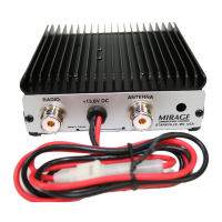
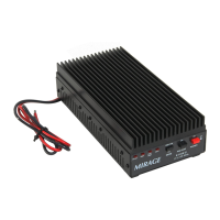
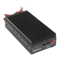
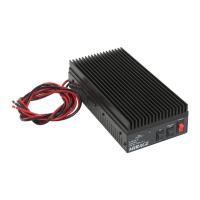
Switch controls amplifier operation: ON for transmit, OFF for receive mode.

DC Input

Connects to 13.8V DC power supply or battery. Red wire is positive, black is negative.

Antenna Connection

Connects antenna directly or via duplexer for dual band operation.

TX RF Input

BNC connector for connecting to the handy-transceiver.

Installation

Precautions

Heat Sink Management

Set amplifier in well-ventilated area during transmission to avoid overheating.

Stabilized Power Supply

Use power supply with sufficient current (7A+) and RF intrusion protection.

Connection Diagram

Operation

Overview

Mirage BD-25 Dual Band Power Linear Amplifier

The Mirage BD-25 is a compact and versatile dual-band power linear amplifier designed for the 144/430 MHz amateur radio bands. It features a maximum output power of 30W and incorporates a cross-band full duplex function, a first in the industry. This innovative design utilizes a new "two band/one RF power transistor" technique, making it a remarkable and useful VHF/UHF dual-band power amplifier.

Key Features:

  • Dual Band Operation: Covers both 144 MHz (VHF) and 430 MHz (UHF) bands.
  • Cross-Band Full Duplex: Allows simultaneous transmission and reception on different bands.
  • Single RF Power Transistor: The transmitter amplifier section uses a single RF power transistor for both VHF and UHF bands.
  • Automatic Frequency Selection: Controlled circuit automatically selects the operating frequency.
  • Reverse DC Power Polarity Protection: Protects the amplifier from damage due to incorrect power connections.
  • VHF/UHF 'On Air' Indicator: LEDs indicate when the amplifier is transmitting on either VHF or UHF.
  • Docking Adaptor System: Compatible with various handy-transceivers through interchangeable docking adaptors.
  • Adjustable Adaptor Power: The adaptor power can be set to 10.8V for newer HT models or 13.8V for older models, or turned off when not in use.
  • Mobile Mounting Bracket: Facilitates easy installation in a vehicle.

Technical Specifications:

  • Frequency: 144 MHz (VHF) / 430 MHz (UHF)
  • Mode: F3 (FM)
  • Input Power: 1-5W
  • Output Power: 50W (Note: The introduction states 30W, while specifications list 50W. This discrepancy may require clarification from the manufacturer.)
  • DC Power Supply: DC 13.8V
  • Current Consumption: 8A (MAX.)
  • Input/Output Impedance: 50 Ohm
  • Input/Output Connector: M TYPE X 2 (SO-239)
  • Dimensions: 3.4(W) x 6.0(H) x 3.4(D) inches
  • Weight: Approximately 1.5 lbs.

Semiconductor Components:

  • RF Power Transistor: X 1
  • Transistors: X 2
  • IC: X 1
  • Diodes: X 8
  • LED: X 5

Included Accessories:

  • Mobile mounting bracket
  • Spare FUSE (8A)
  • Instruction Manual
  • Docking adaptor (specific model may vary or be sold separately)
  • Coaxial jumper cable (M-M)

Usage Features:

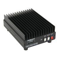
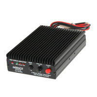
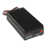
The BD-25 features a straightforward control panel.

  • PWR Indicator: An LED indicates when the amplifier is powered ON and in standby mode.
  • VHF Indicator: An LED illuminates when the amplifier is transmitting on the VHF band.
  • UHF Indicator: An LED illuminates when the amplifier is transmitting on the UHF band.
  • POWER Switch: A two-position switch. In the upper position (ON), the amplifier is ready to transmit (Max. 30W). In the lower position (OFF), the amplifier is in receive mode only.
  • DC INPUT (13.8V): Connects to a stable DC power supply or battery. The red wire (with fuse holder) is positive, and the black wire is negative.
  • ANT Connector: Connects directly to the antenna. For duplex operation, a dual-band antenna (144/440 MHz) tuned on both bands is recommended. Alternatively, two mono-band antennas can be used with a duplexer unit.
  • TX (RF INPUT) Connector: A BNC connector for direct connection to the handy-transceiver.
  • ADAPTER POWER SWITCH: A three-position switch for the docking adaptor power. The middle position turns the adaptor power OFF. The left position provides 10.8V for newer HT models, and the right position provides 13.8V for older HT models.

Operation:

  1. Power On: Turn the power switch to the ON position.
  2. Band Switching: When switching to 144 MHz or 440 MHz transmitting mode, the amplifier automatically detects the transmitting signal frequency of the transceiver and operates accordingly, sending a high-power signal through the antenna. It is crucial to re-confirm the SWR and power using an SWR or power meter at this time.
  3. Crossband Full Duplex: During 144 MHz/440 MHz crossband full duplex operation, minor interference or noise may occur depending on the combination of TX/RX frequencies. Users should select TX/RX frequencies that minimize interference. Particular attention should be paid to 144 MHz band transmission and 440 MHz band reception, ensuring frequencies are not mutually harmonic.

Maintenance and Precautions:

To ensure optimal performance and prevent damage, observe the following:

  • Heat Dissipation: During transmission, the heat sink can reach high temperatures (50°C-80°C). Position the amplifier in a well-ventilated area, avoiding direct sunlight, heaters, or placing objects on top of the unit.
  • Antenna Matching (SWR): Poor antenna matching (high SWR) can hinder efficient power transmission and potentially damage the RF power transistor. Always ensure the antenna is properly connected, free of shorts or opens, and has a low SWR.
  • Input Power: Keep the input power at 5W or less.
  • DC Voltage: Maintain the DC voltage within 12-14V (13.8V nominal). Connecting to a 24V DC battery or AC power source can damage the amplifier.
  • Antenna Connection: Never connect a handy-transceiver's whip antenna directly to the amplifier's antenna connector using an M-BNC converter. This can damage the antenna due to insufficient power capacity and may also harm the transceiver or amplifier from strong RF signal intrusions.
  • Mono Band Antennas: If using a mono-band antenna, verify it matches the transceiver's operating frequency. When using coaxial switches for multiple transceivers/antennas, carefully check the switch position.
  • Coaxial Cable: Use only 50Ω coaxial cable for all connections. Using cables with different impedances (e.g., 75Ω) will cause a mismatch, leading to reflected waves, reduced power output, and potential damage to the RF power transistor.
  • DC Power Supply: When using a stabilized DC power supply, ensure it has sufficient current capacity (7A or more) and good protection against RF signal intrusions. If the power supply malfunctions, discontinue operation, turn off the power switch, and verify connections.
  • Polarity Protection: The amplifier includes internal protection against reverse DC power polarity. However, always double-check the polarity before connecting the power supply, especially when using a battery, to prevent cord damage.
  • Repeater Operation: This unit is not designed for repeater operation, and its use in such service is at your own risk.
  • Internal Adjustments: All internal adjustments are factory set for optimal performance and reliability. Changing internal adjustments may void the warranty.
  • Repair: Improper maintenance or repair can void the warranty. Units requiring repair during the warranty period should be returned to the factory.
  • Cover Removal: Do not operate the unit with the cover removed. The cover confines RF radiation, and the harmonic filters may not suppress direct radiation if the cover is off.

Warranty:

Mirage Communications offers a ONE YEAR LIMITED WARRANTY on the BD-25. Any product found to be defective in materials or workmanship will be repaired or replaced (at Mirage's option) for one year from the date of original purchase. During this period, Mirage Communications will provide parts and labor free of charge. To obtain warranty service, the original purchaser must provide proof of purchase and ship the product in its original container (or equivalent), fully insured and with shipping charges prepaid, to Mirage at the specified address. Mirage assumes no responsibility for items connected to or used with the product. The warranty provides specific legal rights, which may vary by state.

Mirage BD-25 Specifications

General IconGeneral
BrandMirage
ModelBD-25
CategoryAmplifier
LanguageEnglish

Related product manuals