-- -- 4
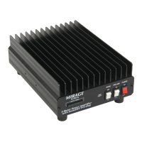
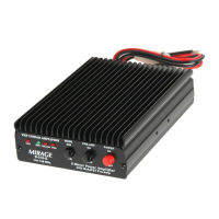
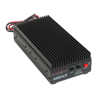
1. VHF INDICATOR
The VHF Indicator LED indicates the amplifier is
transmitting on the VHF Band.
2. UHF INDICATOR
The UHF Indicator LED indicates the amplifier is
transmitting on the UHF Band.
3. PWR INDICATOR
The Power Indicator LED indicates the amplifier is ON
and standing by to transmit.
4. POWER SWITCH
ON (upper position): The amplifier is ready to transmit.
(Max. 30W)
OFF (lower position): The amplifier is on receive mode
only.
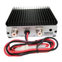
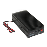
5. DC INPUT (13.8V)
This port has two wires. Connect it to a stable DC power
supply (13.8V) or battery. The red wire has a fuse holder
and is the positive lead. The black wire is the negative
lead. (FUSE holder is on the positive DC lead.)