92 Rev 2.2 • 27 Mar 10
2. Installation
Connecting to Power
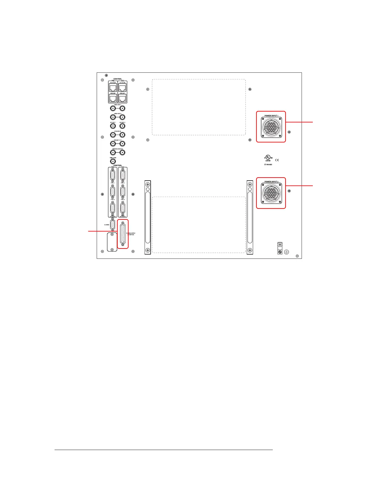
3 Facing the rear of the router, connect the other end of the power cable to ‘Power Input 1’, as
shown in Figure 2-38.
Figure 2-38. NV8576 Power Supply Monitor and Power Supply Connections on Router
4 Similarly, connect the other NV8000 frame (Power Supply 1) to ‘Power Input 2’ using the
WC0096 power cable.
5 Using a WC0046 cable (DB25), connect ‘PS Frame 1 Monitor’ on Power Supply 1 to ‘Power
Supply Monitor’ on the router frame.
6 Using a second WC0046 cable (DB25), connect ‘PS Frame 2 Monitor’ on Power Supply 1 to
‘PS Frame 2 Monitor’ on Power Supply 2.
7 Set the Frame ID switch of Power Supply 1 to ‘1’ and set the Frame ID switch of Power Supply
2 to ‘2’.
8 Connect power cords from AC power sources (90–230 VAC, 50–60 Hz) into power supply con-
nections PS 1 through PS 4. (See Figure 2-37 on page 91.) Connect one power cord for each
PS8100 power supply module you will install.
Power
Input 1
Power
Input 2
Power Supply
Monitor
Connector