NV8500 family Digital Routers • User’s Guide 9
1. Introduction
Signal Rates and Flow
numbered with Output Slot 1 corresponding to outputs 1–18, Output Slot 2 to outputs 19–36, and
so on.
Each card inserted in a slot manages a range of numbers. However, when making physical connec-
tions on the backplanes, each connector has a specific signal number assigned. For details on signal
numbering on backplanes, see Backplane Connectors and Individual Signal Numbers
on page 59.
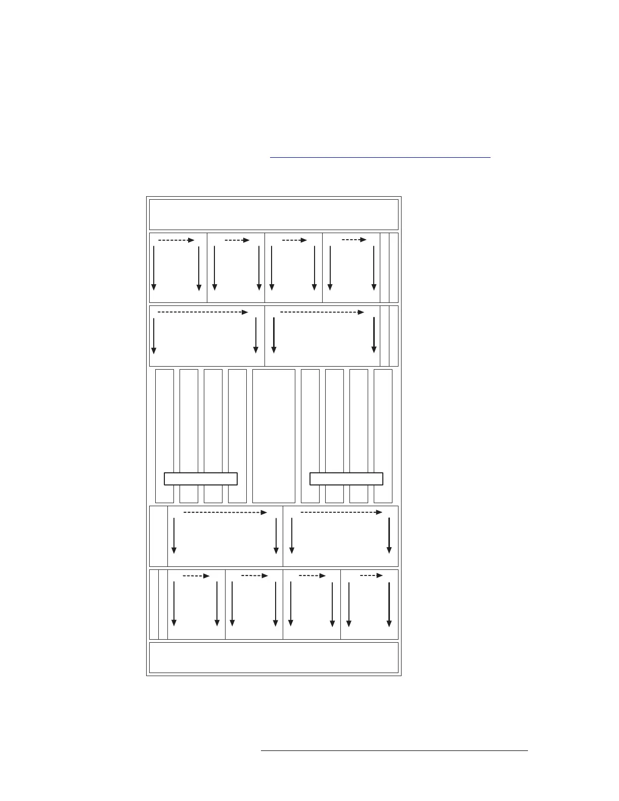
Figure 1-5 shows the standalone NV8576 frame and which signal numbers correspond to which
slots when viewing the router from the front.
Figure 1-5. Example of NV8576 Slots and Corresponding Signal Numbers (Front View)
FAN
OUTPUTS
1144
INPUTS
1144
XPT (INPUTS 1288)
INPUT MONITOR
OUTPUTS
289 432
(8 cards)
OUTPUTS
577720
(8 cards)
OUTPUTS
8651008
(8 cards)
OUTPUT MONITOR
(16 cards)
INPUTS
289 432
(16 cards)
OUTPUTS 1576 OUTPUTS 5771152
OUTPUTS
145 288
(8 cards)
INPUTS
145 288
(16 cards)
INPUTS
433 576
(16 cards)
(not used)
FAN
OUTPUTS
433 576
(8 cards)
OUTPUTS
721864
(8 cards)
OUTPUTS
100 9 1152
(8 cards)
INPUT MONITOR
OUTPUT MONITOR
SEC. CONTROL
PRIM. CONTROL
XPT (INPUTS 1288)
XPT (INPUTS 289576)
XPT (INPUTS 289576)
XPT (INPUTS 1288)
XPT (INPUTS 1288)
XPT (INPUTS 289576)
XPT (INPUTS 289576)
REDUNDANT CROSSPOINT
1
18
127
144
289
306
(8 cards)
432
415
577
703
720
594
865
882
1008
991
1
9
136
144
289
432
297
424
145
153
288
280
433
441
576
568
145
288
433
576
721
864
1009
1152162
271
450
559
738
847
1026
1135